Download
1 / 40
480 likes | 813 Views
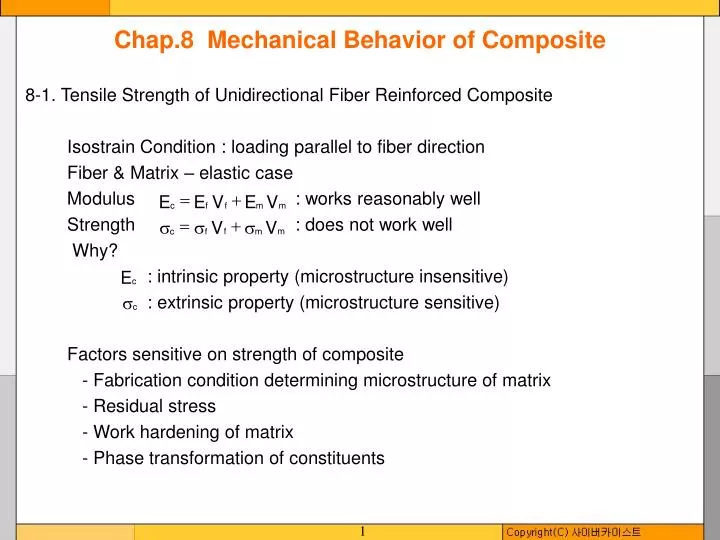
Chap.8 Mechanical Behavior of Composite. 8-1. Tensile Strength of Unidirectional Fiber Reinforced Composite Isostrain Condition : loading parallel to fiber direction Fiber & Matrix – elastic case Modulus : works reasonably well

E N D
Chap.8 Mechanical Behavior of Composite 8-1. Tensile Strength of Unidirectional Fiber Reinforced Composite Isostrain Condition : loading parallel to fiber direction Fiber & Matrix – elastic case Modulus : works reasonably well Strength : does not work well Why? : intrinsic property (microstructure insensitive) : extrinsic property (microstructure sensitive) Factors sensitive on strength of composite - Fabrication condition determining microstructure of matrix - Residual stress - Work hardening of matrix - Phase transformation of constituents
Analysis of Tensile Stress and Modulus of Unidirectional FRC Assumption : Fiber : elastic & plastic Matrix : elastic & plastic Stress-Strain Curve of FRC - divided into 3 stages Stage I : fiber & matrix - elastic → Rule of Mixtures Strength Modulus Stage II : fiber - elastic, matrix - plastic Strength : flow stress of matrix at a given strain Modulus
Stage III : fiber & matrix – plastic Strength UTS : ultimate tensile strength of fiber : flow stress of matrix at the fracture strain of fiber
Effect of Fiber Volume Fraction on Tensile Strength (Kelly and Davies, 1965) Assumption : Ductile matrix ( ) work hardens. All fibers are identical and uniform. → same UTS If the fibers are fractured, a work hardenable matrix counterbalances the loss of load-carrying capacity. In order to have composite strengthening from the fibers, UTS of composite UTS of matrix after fiber fracture Minimum Fiber Volume Fraction As , . As , . degree of work hardening
In order to be the strength of composite higher than that of monolithic matrix, UTS of pure matrix Critical Fiber Volume Fraction As ↓, ↑. As ↑, ↑. degree of work hardening Note that always! (∵ )
8-2. Compressive Strength of Unidirectional Fiber Reinforced Composites Compression of Fiber Reinforced Composite Fibers - respond as elastic columns in compression. Failure of composite occurs by the buckling of fibers. Buckling occurs when a slender column under compression becomes unstable against lateral movement of the central portion. Critical stress corresponding to failure by buckling, where d is diameter, l is length of column.
2 Types of Compressive Deformation 1) In-phase Buckling : involves shear deformation of matrix → predominant at high fiber volume fraction 2) Out-of-phase Buckling : involves transverse compression and tension of matrix and fiber → pre-dominant at low fiber volume fraction Factors influencing the compressive strength : Interfacial Bond Strength : poor bonding → easy buckling
8-3. Fracture Modes in Composites 1. Single and Multiple Fracture Generally, When more brittle component fractured, the load carried by the brittle component is thrown to the ductile component. If the ductile component cannot bear this additional load → Single Fracture If the ductile component can bear this additional load → Multiple Fracture
1) Single Fracture - predominant at high fiber volume fraction - all fibers and matrix are fractured in same plane - condition for single fracture stress beared by fiber additional stress which can be supported by matrix where : matrix stress corresponding to the fiber fracture strain 2) Multiple Fracture - predominant at low fiber volume fraction - fibers and matrix are fractured in different planes - condition for multiple fracture
l 2. Debonding, Fiber Pullout and Delamination Fracture Fracture Process : crack propagation Discontinuous Fiber Reinforced Composite ( lc : critical length ) → Debond & Pullout Good for toughness → Fiber Fracture Good for strength
Fracture of Continuous Fiber Reinforced Composite Fracture of fibers at crack plane or other position depending on the position of flaw ↓ Pullout of fibers For max. fiber strengthening → fiber fracture is desired. For max. fiber toughening → fiber pullout is desired. Analysis of Fiber Pullout Assumption : Single fiber in matrix : fiber radius l : fiber length in matrix : tensile stress on fiber : interfacial shear strength
Force Equilibrium ( lc : critical length of fiber ) 1) Condition for fiber fracture, 2) Condition for fiber pullout,
Load WP Displacement Wd Fracture Process of Fiber Reinforced Composites Real fibers - non-uniform properties 3 steps of fracture process 1) Fracture of fibers at weak points near fracture plane : 2) Debonding of fibers : 3) Pullout of fibers : Outwater and Murphy
Energy Required for Fracture & Debonding elastic strain E. volume Energy Required for Pullout Let k : embedded distance of a broken fiber from crack plane : pullout distance at a certain moment : interfacial shear strength Force to resist the pullout = fiber contact area Total energy(work) to pullout a fiber for distance k Average energy to pullout per fiber(considering all fibers with different k, )
Fracture of Discontinuous Fiber Reinforced Composite → pullout Average energy to pullout per fiber with length, l probability for pullout energy required for pullout Energy for Fiber Pullout vs Fiber Length(l)
As Wd << Wp Advantage of Composite Material: can obtain strengthening & toughening at the same time Toughening Mechanism in Fiber Reinforced Composite 1) Plastic deformation of matrix - metal matrix composite 2) Fiber pullout 3) Crack deflection (or Delamination) - ceramic matrix composite Cook and Gordon, Stresses distribution near crack tip
If > interfacial tensile strength → delamination → crack deflection Delamination Fracture in Laminate Composite Fatigue → debonding at interface Fracture → repeated crack initiation & propagation
8-4. Statistical Analysis of Fiber Strength Real fiber : nonuniform properties → need statistical approach Brittle fiber (ex. ceramic fibers) - nonuniform strength Ductile fiber (ex. metal fibers) - relatively uniform strength Strength of Brittle Fiber → dependent on the presence of flaws → dependent on the fiber length : "Size Effect“ Weibull Statistical Distribution Function : probability density function Probability that the fiber strength is between and . : statistical parameters L : fiber length
Let, : kth moment of statistical distribution function Mean Strength of Fibers Standard Deviation for Strength of Fibers Substituting where : gamma function Coefficient of Variation
As L ↑, ↓. "Size Effect“ As ↑, ↑. is less dependent on L. If , spike distribution function (dirac delta function) → uniform strength independent on L Glass fiber Boron, SiC fibers
# of fibers Strength of Fiber Bundle Bundle strength ≠ Average strength of fiber × n < Assumption : Fibers - same cross-sectional area - same stress-strain curve - different strain-to-fracture Let F(σ) : The probability that a fiber will break before a certain value of is attained. → Cummulative Strength Distribution Function Mean Fiber Strength of Bundle ※ Mean Fiber Strength of Unit Fiber
8-5. Failure Criteria of an Orthotropic Lamina Assumption : Fiber reinforced lamina - homogeneous, orthotropic Failure Criterion of Lamina 1. Maximum Stress Criterion Failure occurs when any one of the stress components is equal to or greater than its ultimate strength. Interaction between stresses is not considered. Failure Condition where : ultimate uniaxial tensile strength in fiber direction (>0) : ultimate uniaxial compressive strength in fiber direction (<0) : ultimate uniaxial tensile strength in transverse direction : ultimate uniaxial compressive strength in transverse direction S : ultimate planar shear strength
x ex) If uniaxial tensile stress is given in a direction at an angle with the fiber axis. Failure occurs when, Failure Criterion 1 2 Failure occurs by a criteria, which is satisfied earlier.
2. Maximum Strain Criterion Failure occurs when any one of the strain components is equal to or greater than its corresponding allowable strain. Failure Condition where : ultimate tensile strain in fiber direction : ultimate compressive strain in fiber direction : ultimate tensile strain in transverse direction : ultimate compressive strain in transverse direction : ultimate planar shear strain
3. Maximum Work Criterion Failure criterion under general stress state Tsai-Hill where X1 : ultimate tensile (or compressive) strength in fiber direction X2 : ultimate tensile (or compressive) strength in transverse direction S : ultimate planar shear strength ex) For uniaxial stress , having angle with the fiber axis Failure criterion substituting
4. Quadratic Interaction Criterion Consider stress interaction effect Tsai-Hahn Stress Function stress term 1st interaction term Thin Orthotropic Lamina i, j = 1, 2, 6 (plane stress) : strength parameters Failure occurs when, → need to know 9 strength parameters For the shear stress components, the reverse sign of shear stress should give the same criterion. ∴
Calculation of Strength Parameters by Simple Tests 1) Longitudinal uniaxial tensile and compressive tests, : longitudinal tensile strength : longitudinal compressive strength 2) Transverse uniaxial tensile and compressive tests, 3) Longitudinal shear test 4) In the absence of other data,
Boron/Epoxy composite Intrinsic properties
8-6. Fatigue of Composite Materials Fatigue Failure in Homogeneous Monolithic Materials → Initiation and growth of a single crack perpendicular to loading axis. Fatigue Failure in Fiber Reinforced Laminate Composites Pile-up of damages - matrix cracking, fiber fracture, fiber/matrix debonding, ply cracking, delamination Crack deflection (or Blunting) Reduction of stress concentration A variety of subcritical damage mechanisms lead to a highly diffuse damage zone.
Constant-stress-amplitude Fatigue Test Damage Accumulation vs Cycles Crack length in homogeneous material - accelerate (∵ increase of stress concentration) Damage (crack density) in composites - accelerate and decelerate (∵ reduction of stress concentration)
S-N Curves of Unreinforced Plolysulfone vs Glassf/Polysulfone, Carbonf/Polysulfone Carbon Fibers : higher stiffness & thermal conductivity higher fatigue resistance S-N Curves of Unidirectional Fiber Reinforced Composites (B/Al, Al2O3/Al, Al2O3/Mg)
Fatigue of Particle and Whisker Reinforced Composites For stress-controlled cyclic fatigue or high cycle fatigue, particle or whisker reinforced Al matrix composites show improved fatigue resistance compared to Al alloy, which is attributed to the higher stiffness of the composites. For strain-controlled cyclic fatigue or low cycle fatigue, the composites show lower fatigue resistance compared to Al alloy, which is attributed to the lower ductility of the composites. Particle or short fibers can provide easy crack initiation sites. The detailed behavior can vary depending on the volume fraction, shape, size of reinforcement and mostly on the reinforcement/matrix bond strength.
Fatigue of Laminated Composites Crack Density, Delamination, Modulus vs Cycles i) Ply cracking ii) Delamination iii) Fiber fatigue
time ModulusReduction during Fatigue Oginetal. ModulusReduction Rate where E : current modulus E0: initial modulus N : number of cycles : peak fatigue stress A, n : constants → linear fitting
Integrate the equation to obtain a diagram relating modulus reduction to number of cycles for different stress levels. → used for material design
8-7. Thermal Fatigue of Composite Materials Thermal Stress Thermal stresses arise in composite materials due to the generally large differences in thermal expansion coefficients() of the reinforcement and matrix. It should be emphasized that thermal stresses in composites will arise even if the temperature change is uniform throughout the volume of composite. Thermal Fatigue When the temperature is repeatedly changed, the thermal stress results in the thermal fatigue, because the cyclic stress is thermal in origin. Thermal fatigue can cause cracking of brittle matrix or plastic deformation of ductile matrix. Cavitation in the matrix and fiber/matrix debonding are the other forms of damage observed due to thermal fatigue of composites. Thermal fatigue in matrix can be reduced by choosing a matrix that has a high yield strength and a large strain-to-failure. The fiber/matrix debonding can only be avoided by choosing the constituents such that the difference in the thermal expansion coefficients of the reinforcement and the matrix is low.