Download
1 / 19
240 likes | 818 Views
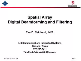
Spatial Array Digital Beamforming and Filtering. Tim D. Reichard, M.S. L-3 Communications Integrated Systems Garland, Texas 972.205.8411 Timothy.D.Reichard@L-3Com.com. Spatial Array Digital Beamforming and Filtering. OUTLINE. Propagating Plane Waves Overview Processing Domains

E N D
Spatial Array Digital Beamforming and Filtering Tim D. Reichard, M.S. L-3 Communications Integrated Systems Garland, Texas 972.205.8411 Timothy.D.Reichard@L-3Com.com
Spatial Array Digital Beamforming and Filtering OUTLINE • Propagating Plane Waves Overview • Processing Domains • Types of Arrays and the Co-Array Function • Delay and Sum Beamforming • Narrowband • Broadband • Spatial Sampling • Minimum Variance Beamforming • Adaptive Beamforming and Interference Nulling • Some System Applications and General Design Considerations • Summary
Using Maxwell’s equations on an E-M field in free space, the Wave Equation is defined as: Monochromatic Plane Wave (far-field): ¶2s + ¶2s + ¶2s = 1. ¶2s k ¶x2¶y2¶z2 c2 ¶t2 x • Governs how signals pass from a radiating source to a sensing array • Linear - so many plane waves in differing directions can exist simultaneously => the Superposition Principal • Planes of constant phase such that movement of dx over time dt is constant • Speed of propagation for a lossless medium is |dx|/dt = c • Slowness vector: a = k/w and |a| = 1/c • Sensor placed at the origin has only a temporal frequency relation: k = Wavenumber Vector = direction of propagation x = Sensor position vector where wave is observed s(xo,t) = Ae j(wt - k. xo) Temporal Freq. Spatial Freq. (|k| = 2p/l) s([0,0,0], t) = Ae jwt Propagating Plane Waves Notation: Lowercase Underline indicates 1-D matrix (k) Uppercase Underline indicates 2-D matrix (R) ¢ or H indicates matrix conjugate-transpose
s(x, t) = s(t - a.x) s(x, t) Space-Time e-jwt ejk.x ejwt e-jk.x S(x, w) S(k, t) Wavenumber - Time Space-Freq e-jk.x ejwt ejk.x e-jwt (or beamspace) Wavenumber - Frequency S(k, w) Processing Domains
# Redundancies Uniform Linear Array (ULA) Co-Array 6 m= 0 1 2 3 4 5 6 4 x 2 d M = 7 origin 0 1d 2d 3d 4d 5d 6d x 2-D Array Co-Array Function: C(c) = S wm1w*m2 m1,m2 x where; m1 and m2 are a set of indices for xm2 – xm1 = c d • Desire to minimize redundancies and • Choose spacing to prevent aliasing Sparse Linear Array (SLA) # Redundancies 4 Co-Array “A Perfect Array” m= 0 1 2 3 3 2 x d 1 M = 4 0 1d 2d 3d 4d 5d 6d x Some Array Types and the Co-Array Function
s(x,t) = e j(wot - ko . x) ko y0(t) w*0 Delay D0 y1(t) w*1 Delay D1 z(t) . . . S . . . yM-1(t) w*M-1 Delay DM-1 Time Domain: M-1 M-1 z(t) = S w*m ym(t - Dm) = ejwot S w*m e-j(woDm +ko. xm) = wHy m=0 m=0 Freq Domain: M-1 M-1 Z(w) = S w*mYm(w,xm) e-j(woDm) = S w*mYm(w,xm) ej(ko. xm) = eHWY m=0 m=0 let Dm = (-||ko|| .xm) / c e is a Mx1 steering vector Ð -||ko|| Delay and Sum Beamformer (Narrowband)
y1(n) z-1 z-1 z-1 w*1,0 w*1,1 w*1,L-1 . . . y2(n) z-1 z-1 z-1 w*2,0 w*2,1 w*2,L-1 . . . yJ(n) z-1 z-1 z-1 . . . w*J,0 w*J,1 w*J,L-1 . . . Delay and Sum Beamformer (Broadband) . . . z(n) S . . . . . . J = number of sensor channels L = number of FIR filter tap weights J L-1 z(n) = SS w*m,p ym(n - p) = wHy(n) m=1 p=0
M-Sensor ULA Interpolation Beamformer(at location xo): y0(n) u’0(n) w0 Delay D0 I y1(n) w1 Delay D1 z(n) I . . . S LPF (p/I) . . . I Down-sample yM-1(n) u’M-1(n) wM-1 Delay DM-1 I Up-sample M-1 z(n) = S wmS ym(k) * h((n-k)T-Dm) k m=0 Spatial Sampling • Motivation: Reduce aberrations introduced by delay quantization • Postbeamforming interpolation is illustrated with polyphase filter
Apply a weight vector w to sensor outputs to emphasize a steered direction (z) while suppressing other directions such that at w = wo: Real {e¢w} = 1 • Hence: min E[ |w¢y|2] yields => wopt = R-1 e / [e¢R-1e ] • Conventional (Delay & Sum Beamformer) Steered Response Power: • PCONV(e) = [ e¢WY ] [ Y¢W¢e ] = e¢ Refor unity weights • Minimum Variance Steered Response Power: • PMV(e) = w¢optRwopt = [e¢ R-1e ]-1 w Minimum Variance (MV) Beamformer • MVBF weights adjust as the steering vector changes • Beampattern varies according to SNR of incoming signals • Sidelobe structure can produce nulls where other signal(s) may be present • MVBF provides “excellent” signal resolution wrt steered beam over the • Conventional Delay & Sum beamformer • MVBF direction estimation accuracy for a given signal increases as SNR increases R = spatial correlation matrix = YY¢
ULA Beamformer Comparison ; w = wo PCONV(z) = [e¢(z) Re(z)] PMV(z) = [e¢(z) R-1 e(z)]-1
Constrained Optimization: min w¢Rw subject to Cw = c Frost GSC† Setup: w y0(l) Adaptive Algorithm y1(l) . . . . . . . . . z(l) S Non-Adaptive wc Adaptive w yM-1(l) Adaptive (Iterative) Portion: • z(l) = w¢(l)y(l) • w(l+1) = wc + P[w(l) - mz*(l)y(l)] †- General Sidelobe Canceller Adaptive Beamformer Example #1 - Frost GSC Architecture • For Minimum Variance let C = e¢, c = 1 • e = Array Steering Vector cued to SOI • R is Spatial Correlation Matrix = y(l)y¢(l) • Rideal= ss¢ + Is2 = Signal Est. + Noise Est. • Determine Step Size (m) using Rideal: • m = 0.1*(3*trace[PRidealP])-1 • P = I - C¢(CC¢)-1C • wc = C¢(CC¢)-1c • w(l=0) = wc
Coherent Interference Signal (7 deg away & 5dB down from SOI) Signal of Interest (SOI) location Shows Signals Resolvable Beam Steered to SOI with 0.4 degree pointing error Setup Info used: • N = 500 samples • M = 9 sensors, ULA with d = l/2 spacing • SOI pulse present in samples 100 to 300 • Co-Interference pulse present in samples 250 to 450 • Aperture Size (D) = 8d • Array Gain = M for unity wm " m Example Scenario for a Digital Minimum Variance Beamformer PMV(z) = [e¢(z) R-1e(z)]-1 M-1 W(k) = S wmej(k.x) m=0
Example of Frost GSC Adaptive Beamformer Performance Results† †- via Matlab simulation
Constrained Optimization: min w¢Rw subject to Cw = c and ||B¢wa||2<b2 - ||wc||2 where b is constraint placed on adapted weight vector Robust GSC y0(l) Setup: w*c(0) Delay D0 • For Minimum Variance let C = e¢, c = 1 • e = Array Steering Vector cued to SOI • B is Blocking Matrix such that B¢C = 0 • Determine Step Size (m) using Rideal: • m = 0.1*(max l BRidealB)-1 • wa = B¢wa • wc = C¢(CC¢)-1c y1(l) w*c(1) Delay D1 . . . z(l) + . . . S S _ yM-1(l) w*c(M-1) Delay DM-1 ~ ~ wa w*a,0(l) Adaptive (Iterative) Portion: S B . . . • yB(l) = By(l) • v(l) = wa(l) + mz*(l)B¢yB(l) • wa(l+1) = v(l), ||v(l)||2 <b2 - ||wc||2 • (b2-||wc||2)1/2v(l)/||v(l)||, otherwise • z(l) = [wc - wa(l)]¢ y(l) w*a,M-1(l) ~ wa ~ LMS Algorithm ~ Adaptive Beamformer Example #2 - Robust GSC Architecture
Example of Robust GSC Adaptive Beamformer Performance Results† †- via Matlab simulation
RMS Phase Noise = 136 mrad RMS Phase Error = 32 mrad Adaptive Beamformer Relative Performance Comparisons • SOI Pulsewidth retained for both; Robust has better response • Robust method’s blocking matrix isolates adaptive weighting to nonsteered response • Good phase error response for the filtered beamformer results • Amplitude reductions due to contributions from array pattern and adaptive portions • The larger the step size (m), the faster the adaptation • Additional constraints can be used with these algorithms • min lPRP is proportional to noise variance => adaptation rate is roughly proportional to SNR
y0(t) DCM BPF Digitizer y1(t) Signal Detection and Parameter Encoding DCM BPF Digitizer Adaptive Beamformer . . . . . . Steering Vector yM-1(t) DCM BPF Digitizer Applications to Passive Digital Receiver Systems • Sparse Array useful for reducing FE hardware while attempting to retain aperture size -> spatial resolution • Aperture Size (D) = 17d in case with d = l/2 and sensor spacings of {0, d, 3d, 6d, 2d, 5d} • Co-array computation used to verify no spatial aliasing for chosen sensor spacings • Tradeoff less HW for slightly lower array gain • Further reductions possible with subarray averaging at expense of beam-steering response and resolution performance
Summary • Digital beamforming provides additional flexibility for spatial filtering and suppression of unwanted signals, including coherent interferers • Various types of arrays can be used to suit specific applications • Minimum Variance beamforming provides excellent spatial resolution performance over conventional BF and adjusts according to SNR of incoming signals • Adaptive algorithms, implemented iteratively can provide moderate to fast monopulse convergence and provide additional reduction of unwanted signals relative to user defined optimum constraints imposed on the design • Adaptive, dynamic beamforming aids in retention of desired signal characteristics for accurate signal parameter measurements using both amplitude and complex phase information • Linear Arrays can be utilized in many ways depending on application and performance priorities
References D. Johnson and D. Dudgeon, “Array Signal Processing Concepts and Techniques,” Prentice Hall, Upper Saddle River, NJ, 1993. V. Madisetti and D. Williams, “The Digital Signal Processing Handbook,” CRC Press, Boca Raton, FL, 1998. H.L. Van Trees, “Optimum Array Processing - Part IV of Detection, Estimation and Modulation Theory,” John Wiley & Sons Inc., New York, 2002. J. Tsui, “Digital Techniques for Wideband Receivers - Second Edition,” Artech House, Norwood, MA, 2001.