Download
1 / 35
350 likes | 475 Views
Adaptive Space Deformations Based on Rigid Cells. Interactive Skeleton-Driven Dynamic Deformation. Catalin Constantin. Overview and Facts Formulation Basics Hierarchical Basis Equations of Motion Numerical Integration Implicit Solution Imposing Bone Constraints

E N D
Adaptive Space Deformations Based on Rigid Cells Interactive Skeleton-Driven Dynamic Deformation • Catalin Constantin
Overview and Facts • Formulation Basics • Hierarchical Basis • Equations of Motion • Numerical Integration • Implicit Solution • Imposing Bone Constraints • Linear Subspace Constraints • Blended Local Linearization • Twist Constraints • Simulation Step Example Interactive Skeleton-Driven Dynamic Deformation
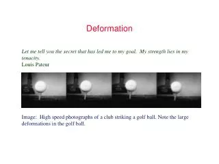
creating realistic character animations that support physically based secondary motions. Plain-old key framing doesn’t go too far • shape movement/deformation controlled by line segment based skeletons Overview and Facts • supports line constraints (along with bone constraints), multiresolution, and bended local linearization for non-linear constraints
objects represented as a domain in space • motion of the object is a time dependent mapping function p, such that: Formulation Basics (1) instrument each object with a skeletal complex S (with joints and bones) interior to the object • are mappings of a generic point in the object and, respectively, of a special point of the skeletal structure.
given the mapping functions: • p(x,t) results from a PDE system subject to the bone constraints • rigidity of the bones implies piecewise linear constraints • for numerical integration we apply FEM and separate the mapping p(x,t) into a rest stater(x), and a dynamic displacement, time dependent, d(x,t). Formulation Basics (2) • * whenever a term contains the same index as both a subscript and a superscript it is assumed to represent a finite sum of that domain.
used to allow simulation to adapt to local conditions (increase resolution where needed) • basis B defined in terms of repeated subdivisions of the control lattice K Hierarchical Basis • Edges of S (bones) are edges of cells of K, and their basis coefficients reduce to unity. This means that representation of transformed vertices of S are simplified as:
Model embedded in (half) control lattice • Skeleton coincides with lattice edges and vertices Hierarchical Basis (complex objects) • Regions for local linearization; notice color blending where regions overlap (near joints) Model instrumented with a skeleton and local coordinate systems at joints
Equations of motion are the Euler-Lagrange equations: Equations of Motion (1) • gradient of T in respect to the time derivative of q • gradient of V in respect to q based on representation in equation (1), we can express kinetic energy T and potential elastic energy V as functions of q and its time derivative. • generalized external force, such as gravity • generalized dissipative force to simulate friction • Next we’ll see how we can actually use each of these
the Kinetic Energy of a moving body is a generalization of the very familiar scalar form: • after further differentiation and simplification: Equations of Motion (2) I. Kinetic Energy Formulation: • which is the first term of the Euler-Lagrange equation of motion
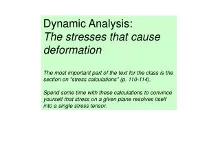
the Elastic Potential Energy captures the amount of work required to deform the body from the rest shape to its current shape, and it depends on: • the strain tensor (degree of metric distortion, Green’s strain tensor is a standard measure of strain) Equations of Motion (3) • the stress tensor (defined in terms of stress) II. Potential Energy Formulation (a): • where G is called shear modulus or modulus of gravity, and ʋ is called Poisson ratio (the extent to which strains in one direction are related to those perpendicular to it)
eluding some derivation steps which are not essential to our lecture, the final form of the Elastic Potential Energy in terms of stress and strain: • a more meaningful relation used in the integration step is the relationship between V and a matrix based on the strain and stress tensors, called stiffness matrix S: Equations of Motion (4) • whose representation in derivative form can be substituted in the numerical integration step II. Potential Energy Formulation (b):
treat gravity as a constant acceleration field and compute the potential energy it produces on the body. It will be a value in terms of g and (sometimes) q • IV. Dissipative force (friction) Equations of Motion (5) • The friction simulation effect is already a measure in terms of the time derivative of q and can be used directly in the numerical integration step III. External force (such as gravity)
subdivide K to the desired level for numerical integration • compute the value of the basis function at each vertex • tetrahedralize the domain. After the first subdivision we have a hexahedral domain. After another subdivision we get tetrahedral cells • compute the integrals over each domain cell using piecewise approximations to the basis functions. When all four vertices of a tetrahedron fall outside, its contribution is neglected Numerical Integration • solving the system? – linearize the equations of motion at the beginning of each timestep and apply an implicit solver to the equations of motion • Next, a quick review of the Second Order Implicit Solution
introduce v and solve as a system: Implicit Solution (1) • based on Euler step express change as: general form of second-order dynamics equation is:
substitute (f) and (d) into (e) and we get: Implicit Solution (2) • regrouping, we obtain the following solution (the second variant is for the case when we have dependency of f on time): using Taylor expansion of a function of two variables:
apply the strategy to our equations of motion Implicit Solution (3) starting from the previous solution pair: • Now let’s work some details that may look scary …
… and here is the solution Implicit Solution (4) • all quantities are evaluated at the beginning of the timestep • the last equation is a sparse linear system that can be solved using a CG (Conjugate Gradients) solver • ∆vis then substituted in the first equation to get ∆q
from simulation point of view, the skeleton is simply a complicated constraint • because bones lie along the lattice, their equations are easy to handle algebraically. A simplified version of the last equation is: A ∆v = b, and∆v contains both known values (from the control points) and unknown values (from all other points). Imposing the Bone Constraints in this framework the skeleton is controlled by keyframe data, or by some external control • Adding skeletal constraints actually reduces the computational cost by shrinking the system
the displacement at certain points conforms to a known function d. Evaluating the fist equation of the solution pair we obtain an expression which can be computed at the beginning of each timestep: Linear Subspace Constraints caused by interaction with other objects. We can impose position constraints at any point in a continuous body
to successfully apply this on articulated characters, we note that they only undergo large deformations around joints. We subdivide in regions, and assign weights to the control vertices. Each region has an associated function space whose weight coefficients produce most impact to the points in that region Blended Local Linearization The bottleneck of this model is computation of the stiffness matrix at the beginning of each time step • solution? Linearize the strain tensor (drop last term) which yields a constant stiffness matrix and works fine for small deformations. Why is that satisfactory? What about big deformations?
Twisting Constraints flesh can rotate about a line constraint if no special measure is applied yielding unnatural free movement • solution? Introduce constraint to penalize all displacement within certain fixed radius of the bones
One Simulation Step extract regional variables from global system convert q to the displacement from the transformed rest shape (T is the transform of the bone associated to region) builds the linear system solve the linear system CG solver solution merged from each region according to weights assigned by the user/external update global state 1 update global state 2 • Qi is a rectangular matrix to select basis functions that have nonzero restrictions on region i
Overview and Facts • Formulation Basics • Nonlinear Optimization • Adaptive Space Discretization • Space Deformation • Results, Limitations, and To Do’s Adaptive Space Deformations Based on Rigid Cells
physically inspired volumetric shape deformation based on simplified elastic energy formulation • works with any kind of convex cells. Fast discretization update supported by underlying data structure (octree) Overview and facts contrasted with surface-based deformations which, even though computationally less intensive, tend to alter certain features such as local/global volume. • support for arbitrary sample based surface representations (meshes, triangle soups, point clouds, etc.)
Formulation Basics (1) • elastic strain energy for deformable objects is typically defined in terms of the gradient of the displacement function • in contrast with FEM based models where individual cells are deformed, this approach wants to preserve cells rigid for the sake of numerical robustness and to model deformation energy based on an elastic glue that couples adjacent cells.
when two adjacent cells are displaced from their initial positions by rigid motions (transforms) Ti and Tj, we can define the elastic energy in terms of square distances of a set of representative sample points between the two transforms. Formulation Basics (2) • which sample points are best? If possible … all! For simple shapes that are easy to integrate analytically it works quite well.
global energy for the cell complex is defined as a weighted average of the piecewise energies (1) for all pairs of adjacent cells. • weights depend on the area of the (partially) shared face and perpendicular distanced to the face from the centers of mass. Formulation Basics (3) • * in case of an adaptive hexahedral face the perpendicular is half the voxel size, and face area uses the min of the two voxel sizes
Interaction with the model is done by selecting • a deformable region (blue in the first image) • a fixed region (gray in the first image) • one or several handles (yellow in the first image) • Handles can then be transformed using any existing modeling interface. • Each cell stores a rigid motion. It can either be prescribed both rotation and translation, or be fixed at a point and allowed to rotate only. Nonlinear Optimization (1) • Elastic energy minimized by finding optimal rigid motions for the remaining, unconstrained cells. Equivalent to a geometric shape matching problem – good for Newton-type solver
in each iteration of the Newton solver we linearize the rigid motions by linear and angular velocities which yield affine approximations, resulting in an energy function quadratic in the linear and angular velocities: Nonlinear Optimization (2) • minimizing this energy by solving a sparse linear system yields optimal affine motions Ai corresponding to tangent vectors on the manifold of rigid motions that yield a descent direction. The resulting Ai affine motions must be projected on their closest rigid motions amounting to a local shape matching.
regular grids are an obvious choice, they are capable of sustaining smooth, large scale deformations, but they do not scale well • octree-like refinement based on hexahedral cells with an initial coarse, regular grid, and with the ability to subdivide in areas of high deformation were used. Adaptive threshold – dynamic refinement scheme based on geometric error • elastic energy provide strain measure and helps calculate local response based on global information of the surrounding cells (through pairwise elastic energy measure) Adaptive Space Discretization
every cell of the space decomposition defines a local transform that maps the cell center from its original position ci to the deformed position T(ci). • build a continuous space deformation function by interpolating the point transforms • choose an advanced interpolation scheme (i.e. triharmonic RBF), which can give fairly efficient non uniform node placement • To maintain interactive response during real time simulation (user drags the mouse to produce deformation), use a simpler blending function (i.e. averaging the transforms of the four closest cells), and then perform the in-depth corrections once the real time responsiveness is not necessary anymore (mouse release) Space Deformation
simplified editing model, in depth analysis once the general shape was agreed upon. • more natural deformations that FEM with explicit volume control • limitation on aliasing • handle a modest number of cells at interactive rate • compared to the linear approach, this one requires considerably more resources Results, Limitations, and To Do’s (1) • octree decomposition directly supports hierarchical solvers, could map well on GPUs for better performance
[1] Botsch M., Pauly M., Wicke M., Gross M.: Adaptive Space Deformations Based on Rigid Cells. Eurographics 2007. [2] Capell S., Green S., Curless B., Duchamp T., Popovic Z.: Interactive Skeleton-Driven Dynamic Deformations. Proc. of SIGGRAPH 2002. [3] Capell S., Green S., Curless B., Duchamp T., Popovic Z.: A Multiresolution Framework for Dynamic Deformations. University of Washington, department of computer Science and Engineering, Technical Report 02-04-02. References [4] Baraff D., and Witkin A.: Large Steps in Cloth Simulation. Computer Graphics. (Proc. SIGGRAPH), 1998 [5] Weber O., Sorkine O., Lipman Y., and Gotsman C.: Context-Aware Skeletal Shape Deformation. (Proc. EUROGRAPHICS), 2007