Download
1 / 44
440 likes | 514 Views
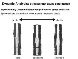
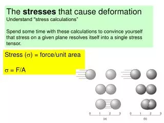
Dynamic Analysis: The stresses that cause deformation The most important part of the text for the class is the section on "stress calculations" (p. 110-114). Spend some time with these calculations to convince yourself that stress on a given plane resolves itself into a single stress tensor.

E N D
Dynamic Analysis: The stresses that cause deformation The most important part of the text for the class is the section on "stress calculations" (p. 110-114). Spend some time with these calculations to convince yourself that stress on a given plane resolves itself into a single stress tensor.
Stresses 1) Normal stress Positive or negative 2) Shear stress Positive or negative
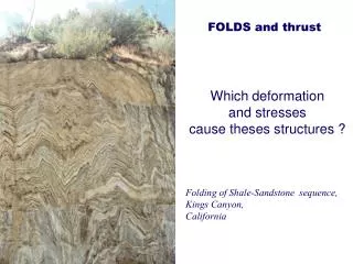
Responses to Stresses 1) Folding 2) Brittle faults 3) Ductile shear zones 4) Joints
Concept of Dynamic Analysis The goals of dynamic analysis are: 1) Interpret the stresses responsible for deformation. 2) Describe the nature of the forces that cause the stresses. 3) Understand the relations between stress, strain and rock strength. Describing stress and force is a mathematical exercise. Dynamic analysis is about the relations between the stresses that cause deformation and the rock’s strength, which tends to resist that deformation.
Force Force: changes in the state of rest or motion of a body. Only a force can cause a stationary object to move or change the motion (direction and velocity) of a moving object. force = mass x acceleration, F = ma, mass = density x volume, m =rV, therefore, r = m/V, Weight is the magnitude of the force of gravity (g) acting upon a mass. The newton (N) is the basic (SI) unit of force. 1 newton = 1 kg meter/sec2 1 dyne = 1g cm/sec2 so 1 N = 105 dyne 1 pascal = newton/m2
Forces as Vectors Force is a vector - it has magnitude and direction. Vectors can be added and subtracted using vector algebra. We can evaluate vectors in order to determine whether the forces on a body are in balance. Load Force
Forces in the Geologic World Typically we think of the Earth as at rest - in static equilibrium, or moving very slowly. When there are net forces, they cause accelerations that are usually one of 2 kinds: 1) slow ponderous motion of a tectonic plate that increases or decreases velocity over a very long time, or; 2) sudden, short lived, strong accelerations during fault slip accompanying earthquakes.
Two types of Forces Body forces, that act on the mass of a body (gravity, electromagnetic), and are independent of forces applied by adjacent material, and; 2) Contact forces, are pushes and pulls across real or imaginary surface of contact such as faults. Three different type of loading due to contact forces: 1) gravitational loading - pushing on adjacent rock. 2) thermal loading - expansion or contraction. 3) displacement loading - push due to motion.
Stress(s) Stress is force per unit area: s= F/A
Units of Stress 1 newton = 1 kg meter/sec2 = this is a unit of force 1 dyne = 1g cm/sec2 so 1 N = 105 dyne 1 pascal = 1 newton/m2 = unit of stress • 1 newton is about 0.224 809 pounds of force • 1 dyne is about 2.248 x 10⁻⁶ pound of force • 1 pascal is about 0.020 885 lb/ft2, thus pressure is measured in kPa • 1 kPa = 0.145 lb/in2 • 9.81 Pa is the pressure caused by a depth of 1mm of water
Stress Underground (Pressure) 1) You are underground at 1000 meters depth. 2) Overlain by a huge cube of granite (1 km x 1 km x 1 km) 3) Calculate stresses at the base of the granite 4) Volume of block = 1000m x 1000m x 1000m times 5) Density of the granite (r)= 2700 kg/m3 times 6) Acceleration due to gravity (g) = 9.8 m/s2
Stress Underground (Pressure) • The stress created by the weight of the block of granite acting on the base of the block is determined by dividing the force (F) by the area (A = 1000m x 1000m) • = F/A = 24,460,000 Pa = 24 MPa • This tells us about the lithostatic stress gradient at depth. • F = 1000m x 1000m x 1000m x 2700 kg/m3 x 9.8 m/s2 • = F/A = 1000m x 1000m x 1000m x 2700 km/m3 x 9.8 m/s2 • 1000m x 1000m
Stress Underground (Pressure) • The stress created by the weight of the block of granite acting on the base of the block is determined by dividing the force (F) by the area (A = 1000m x 1000m) • = F/A = 24,460,000 Pa = 24 MPa • This tells us about the lithostatic stress gradient at depth. Shortcut, s = rgh = 2700 km/m3 x 9.8 m/s2 x 1000m = 26.5 Mpa • F = 1000m x 1000m x 1000m x 2700 kg/m3 x 9.8 m/s2 • = F/A = 1000m x 1000m x 1000m x 2700 km/m3 x 9.8 m/s2 • 1000m x 1000m
Stress Underground (Pressure) s=26.5 MPa This tells us about the lithostatic stress gradient at depth. It increases 26.5 MPa per km, equivalent to 265 bars or 0.265 kbar/km. So for each 3.8 km depth, lithostatic stress increase by 1 kbar or 100 MPa (same as under 10 km of ocean water)
Stress is a Traction To be more accurate, stress is a traction. A traction is a stress acting upon a surface. 'Stress' is a whole collection of stresses acting upon on every conceivable plane in every conceivable orientation at an infinitesimally small point (P). From now on we will use the term 'stress' when actually referring to a 'traction'. We will use the term 'stress tensor' when referring to the many tractions of stress
Stress on a dipping plane in the Earth’s crust 2 components Normal stress & Shear stress
Look inside granite at a plane that is inclined 65°. B. Block diagram of dipping plane. What are the total stresses acting on the xz plane, sxz? Vertical s = 40 MPa, Horizontal s = 20 MPa What are the normal and shear stresses acting on the 65° plane?
D. Calculated stress values acting parallel to x and z. Sx = 20 MPa x area (cos 65°) Sz = 40 MPa x area (sin 65°) Sz = 36.2 MPa and Sx = 8.45 MPa • Balance of forces acting on the parcel of rock. Components of stresses acting on xz plane are: • sz = 40 MPa, • sx = 20 MPa • Sx and Sz, stress component acting on the dipping plane So, xz2 = (Sx)2 + (Sz)2 = (8.4 MPa)2 + (36.2 MPa)2 = 37.2 MPa
Stresses Normal stress Shear stress
Stresses 1) Normal stress Positive or negative 2) Shear stress Positive or negative
We resolve stress into two components • Normal stress, sn and the component that is parallel to the plane, shear stress, ss • Normal compressive stresses tend to inhibit sliding along the plane and are considered positive if they are compressive. • Normal tensional stresses tend to separate rocks along the plane and values are considered negative. • 3) Shear stresses tend to promote sliding along the plane, labeled positive if its right-lateral shear and negative if its left-lateral shear.
Two components of stress The acute angle q between sxz and plane XZ is +78°. The angle is positive, measured clockwise from plane to the stress direction. Numerical solution is easy. sN= sxzsinq = 37 Mpa x sin78° = 36 Mpa ss= sxzcosq = 37 Mpa x cos78° = 7.7 Mpa
Stress ellipsoid If we plot all the stress vectors such that their tails meet at a common point (the point containing the planes for which we originally computed the vectors, its common point). If we plot this to scale an elliptical picture is generated, called the stress ellipsoid. It is useful for describing the state of stress in any point within a body of rock. Vector has magnitude and direction
The data are so systematic, that if we plot all the stress arrows, scaled properly, we generate a stress ellipse. The X and Y axes of the stress ellipse are called principal stress directions. They are always mutually perpendicular. The long axis is the axis of greatest principal stress, called s1. The short axis is the axis of least principal stress, s3. Theses two axes define the stress ellipse. With a three dimensional analysis of stresses, we use a stress ellipsoid, here we have an axis of intermediate stress, called s2. These are all mutually perpendicular.
The long axis is the axis of greatest principal stress (s1) and the short axis is the axis of least principal stress (s3). These axes define the stress ellipse. The intermediate principal stress is oriented perpendicular to the plane of s1&s3and is called s2. The ellipse changes shape depending on the values of the principal stresses.
Hydrostatic Stress If we calculate stress vectors within a point of a hydrostatic stress field, we find that the stress vectors have the same value. Each stress vector is oriented perpendicular to the plane. All stress vectors are normal vectors, they have no shear stress components. See p. 117, the special case of Hydrostatic Stress. Equal stress magnitudes in all directions. Dive into a pool. All stresses have the same values. Hydrostatic stress = all principal stresses in a plane are equal in all directions. No shear stresses!
Hydrostatic Stress Stress parallel to x and y axis is the same, 12 MPa. The single stress, s has a magnitude of 12 MPa and is oriented perpendicular to the plane. This stress, s has no shear stress.
Stress We resolve stress into two components. Normal stress,snand the component that is parallel to the plane, shear stress,ss. sncan be compressive or tensile. The X and Y axes of the stress ellipse are called principal stress directions. They are always mutually perpendicular. The long axis is the axis of greatest principal stress, calleds1. The short axis is the axis of least principal stress,s3. Theses axes define the stress ellipse. Deviatoric stress Hydrostatic stress = all principal stresses in a plane are equal in all directions. No shear stresses!
The Stress equations We need the greatest and least principal stresses in order to calculate normal and shear stresses on any given dipping plane We can calculate the normal and shear stresses on a plane of any orientation using these equations.
Picture of vertical (sz) and horizontal stress (sx) of 12 MPa. The lines are traces of planes at 5° intervals. Stress for each plane have been calculated. What is the state of stress?
Stress ellipse created by arranging all the calculated stresses (s) and arranging them so their tips meet at a point. The length of each stress is the same in hydrostatic state of stress. Stress ellipse created by arranging all the calculated stresses (s) and arranging them so their tips meet at a point. The length of each stress arrow is different in non-hydrostatic state of stress (differential stress).
Stress Normal stress Shear stress Calculating normal and shear stress values sS = sxzcosq sN = sxzsinq The acute angle q lies between the total stress (sxz) and the XZ plane.
Stresses 1) Normal stress Positive or negative 2) Shear stress Positive or negative
The Stress equations We need the greatest and least principal stresses in order to calculate normal and shear stresses on any given dipping plane We can calculate the normal and shear stresses on a plane of any orientation using these equations. sN = 40 MPa + 20 MPa - 40 Mpa – 20 Mpa (cos 60°) (where q = 30°) 2 2 sN = 30 Mpa – 10 MPa(0.5000) sN = 25 MPa sS = 40 MPa – 20 MPa(sin 60°) sS = 10 MPa (0.8660) sS = 8.6 MPa
Mohr Stress Diagram • This give us a useful picture or diagram of the stress equations. • b) They describe a circular focus of paired values, N&S, the normal and shear stresses that operate on planes of any and all orientations. • c) Using a Mohr stress diagram, we can identify a plane of any orientation relative to 1 and read the values of normal (N) and shear stress (S) acting on the plane.
Principal normal values of s1 & s3 are plotted on the axis of the diagram. A circle is drawn between these two points, such that s1 - s3 constitute the circles diameter. If 1 = 40 MPa and 3= 20 MPa, all paired values of N&S exist for points on the perimeter of the circle. Use angle =30°, with a radius on a unit circle, its 2 equals 60°. is the angle between the greatest principal stress (1) and the dip of the plane Where the radius intersects the perimeter of the circle is a point whose x, y coordinates are the N&S for the plane in question.
The center of the Mohr stress circle = mean stress (the hydrostatic component of the stress field. Hydrostatic stress produces dilation. The radius of the circle represents the deviatoric stress or the non-hydrostatic stress component. Deviatoric stress produces distortion. The diameter of the circle represents differential stress. The large the differential stress, the greater potential for distortion.
Angle is the angle between greatest stress component and the plane. Double the angle, plot as 2 Mohr stress circle convention. What is 1 and 3? What is n and s? And what’s the deal with positive versus negative values?
What is angle ? It is the dip of the plane! What is 1 and 3? What is n and s? And what’s the deal with positive versus negative values?
Various states of stress Hydrostatic stress, a single point on the Mohr circle that lies on the x-axis. All normal stresses are the same, and no shear stresses. Uniaxial stress, two of the three principal stresses are zero. The circle passes thru the origin. The part of the circle that lies to the right of the shear stress axis is compressive, to the left is tensile. Axial stress, all three principal stresses are non-zero, but two of the principal stresses have the same value. Typical stress ellipse. Triaxial stress, all three principal stresses are different.