Download
1 / 32
330 likes | 338 Views
Dynamic Data Driven Finite Element Modeling of Brain Shape Deformation During Neurosurgery. A. Majumdar 1 , D. Choi 1 , P. Krysl 2 , S. K. Warfield 3 , N. Archip 3 , K. Baldridge 1,4 1 San Diego Supercomputer Center & 2 Structural Engineering Dept University of California San Diego

E N D
Dynamic Data Driven Finite Element Modeling of Brain Shape Deformation During Neurosurgery A. Majumdar1, D. Choi1, P. Krysl2 , S. K. Warfield3, N. Archip3 , K. Baldridge1,4 1 San Diego Supercomputer Center & 2 Structural Engineering Dept University of California San Diego 3 Computational Radiology Lab Brigham and Women’s HospitalHarvard Medical School 4 Universität Zürich Grants: NSF: ITR 0427183, 0426558; NIH:P41 RR13218, P01 CA67165, LM0078651, I3 grant (IBM)
Contents of Talk • Overview of Image Guided Neurosurgery and Dynamic Data Drive Application System • Biomechanical FEM solution • Briefly grid scheduling • Future : near-continuous DDDAS
Overview of Image Guided Neurosurgery and Dynamic Data Drive Application System
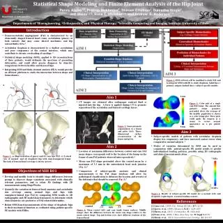
Neurosurgery Challenge • Challenges : • Remove as much tumor tissue as possible • Minimize the removal of healthy tissue • Avoid the disruption of critical anatomical structures • Know when to stop the resection process • Pre-op MRI compounded by the intra-operative brain shape deformation as a result of the surgical process • Important to quantify and correct for these deformations while surgery is in progress • Real-time constraints – provide images ~once/hour within few mins during surgery lasting ~6 hours
Brain Deformation Before surgery After surgery
Tumor Ventricles Intra-operative image, after dura opened and partial tumor resection Pre-operative Image
Preoperative data Intraoperative MRI Segmentation Registration Solve biomechanical Model for volumetric deformation Surface matching Visualization Guide surgical process Overall Process Before image guided neurosurgery During image guided neurosurgery Preoperative Data Acquisition Segmentation and Visualization Tetrahedral FE mesh Preoperative Planning of Surgical Trajectory
Timeline of Image Acquisition and Analysis Time (min) Action 0 20 30 10 40 Before surgery Duringsurgery Preopprocesses IntraopMRI Segmentation Registration Surfacedisplacement Biomechanicalsimulation Visualization Surgicalprogress
Pre- and Intra-op 3D MRI (once/hr) Segmentation, Registration, Surface Matching for BC Intra-op surgical decision and steer Once every hour or twofor a 6 hour surgery Local computer at BWH Merge pre- and intra-op viz Crude linear elastic FEM solution Current DDDAS (Dynamic Data Driven Application System)
Two Research Aspects • Parallel solution of the linear elastic biomechanical model for brain shape deformation during surgery • Grid Architecture – grid scheduling, on demand remote access to multi-teraflop machines, data transfer/sharing
Brief Concept of Biomechanical Model Assuming a linear elastic continuum with no initial stress or strains, the deformation energy of an elastic body submitted to eternally applied forces : F = F(x,y,z) is the vector representing the force applied to the elastic body u = u(x,y,z) is the displacement vector field we want to compute is the strain vector = Lu and the stress vector linked to the strain vector by the material constitutive equation. Linear isotropic elastic brain tissue is modeled with two parameters: Young’s elasticity modulus and Poisson’s ratio. Introducing FE and some analysis, Ku = -F (K is the rigidity matrix) The displacements at the boundary surface nodes are fixed to match those generated by the deformable surface model.
Current and New Biomechanical Models • Current linear elastic material model RTBM • Advanced biomechanical model FAMULS (AMR) • Advanced model is based on conforming adaptive refinement method • Inspired by the theory of wavelets this refinement produces globally compatible meshes by construction • Replicate the linear elastic result produced by RTBM using FAMULS
FEM Mesh : FAMULS & RTBM RTBM (Uniform) FAMULS (AMR)
Deformation Simulation After Cut No – AMR FAMULS RTBM 3 level AMR FAMULS
Petsc setup • PetscMapCreateMPI(PETSC_COMM_WORLD,PETSC_DECIDE,n,&map) ; • MatCreateMPIAIJ(PETSC_COMM_WORLD,..&K_global) ;
Domain decomposition • PetscMapGetLocalRange(map,&Istart,&Iend) • for (each elements) {for (each dof in each nodes is in (lstart, lend)) if it is in the rage { ComputeShape(); ComputeBD(); MatSetValues(K_global,..ADD_VALUES); } }
Boundary condition • Prescribed forces: VecSetValues(F_global, nodeForces->NIndices, nodeForces->Indices, nodeForces->Displacements, ADD_VALUES); • Prescribed displacements: (displacements on the surface obtained by active surface algorithm) MatZeroRows(K_global,ISBoundaryNodes,&one); VecSetValues(F_global, bc->NIndices,bc->Indices, bc->Displacements,INSERT_VALUES);
Solver setup • KSPCreate(PETSC_COMM_WORLD,&ksp) • KSPSetOperators(ksp,K_global,K_global..) • KSPGetPC(ksp,&pc) • PCSetType(pc,PCBJACOBI) • KSPSetTolerances(ksp,1.e-7..) • KSPSetFromOptions(ksp) • KSPSolve(ksp,F_global,u_displ,&its)
IBM Power3 IA64 TeraGrid IBM Power4 Parallel RTBM Performance (214035 tetrahedral elements) 60.00 50.00 40.00 Elapsed Time (sec) 30.00 20.00 10.00 - 1 2 4 8 16 32 # of CPUs
Advanced Biomechanical Model • The current solver is based on small strain isotropic elastic principle • New biomechanical model • Inhomogeneous scalable non-linear hyper-elastic or visco-elastic model with AMR • Increase resolution close to the level of MRI voxels i.e. millions of FEM meshes • New high resolution complex model still has to meet the real time constraint of neurosurgery • Requires fast access to remote multi-teraflop systems
On-demand Scheduling Experiment on 5 TeraGrid Clusters • The real-time constraint of this application requires that data transfer and simulation altogether take about 10 mins, otherwise these results are not of use to surgeons • Assume simulation and data transfer (both ways) together takes 10 mins and data transfer takes 4 mins • Leaves 6 mins for biomechanical simulation on remote HPC machines • Assume biomechanical model is scalable i.e. better results achieved on higher number of processors • Objective : • Get simulation done in 6 mins • Get maximum number of processors available within 6 mins • Allow 4 mins to wait in the queue; this leaves 2 mins for actual simulation
Experiment Characteristics • Flooding scheduler approach – experiment 1: • Simultaneously submit 8, 16, 32, 64, 128 procs jobs to multiple clusters - SDSC DataStar, SDSC TG, NCSA TG, ANL TG, PSC TG • When a higher count job starts (at any center) kill all the lower CPU count jobs at all the other centers • Results : out of 1464 job submissions over ~7 days, only 6 failed giving success of 99.59%; 128 CPU jobs ran greater than 50% of time; at least 64 CPU jobs ran more than 80% of time • Next slide gives time varying behavior with 6 hour intervals for this experiment • 4 other experiments were performed by taking out some of the successful clusters as well as taking scheduler cycle time into account on DataStar • As number of clusters were reduced, success rate goes down
Current DDDAS vs. (future) near-continuous DDDAS • Problem of current DDDAS: • Using current DDDAS procedure, surgeon does not have near-continuous brain deformation info • It takes more than 20 minutes to have whole 3d scan, segmentation, surface matching and FEM solution • Solution is to extend to near continuous DDDAS: • DDDAS approach to provide near-continuous closed loop registration updates using near-continuous 2D MRI slice scans