Download
1 / 51
510 likes | 711 Views
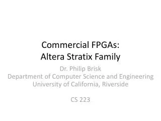
ALTERA FPGAs and NIOSII. ELG6158 Computer Systems Architecture Miodrag Bolic. Presentation Outline. Basic description of Stratix Altera Devices NIOS II processor architecture How to design a system using NIOS II processor. Stratix EP1S10 [2]. TriMatrix™ Memory [1].

E N D
ALTERA FPGAs and NIOSII ELG6158 Computer Systems Architecture Miodrag Bolic
Presentation Outline • Basic description of Stratix Altera Devices • NIOS II processor architecture • How to design a system using NIOS II processor
TriMatrix™ Memory [1] Dedicated External Memory Interface M512 Blocks M-RAM M4K Blocks • Packet / Data Storage • Nios Program Memory • System Cache • Video Frame Buffers • Echo Canceller Data Storage • Small FIFOs • Shift Register • Rake Receiver Correlator • FIR Filter Delay Line • Header / Cell Storage • Channelized Functions • ATM cell–packet processing • Nios Program Memory • Look-Up Schemes • Packet & Cell Buffering • Cache More Bits For Larger Memory Buffering 512 Kbits per block + parity 4 Kbits per block + parity 512 bits per block + parity More Data Ports for Greater Memory Bandwidth
LE1 LE2 LE3 LE4 LE5 LE6 LE7 LE8 LE9 LE10 Logic Array Blocks (LAB) [2] Control Signals • 10 LEs • Local Interconnect • LAB-Wide Control Signals 4 4 4 4 4 Local Interconnect 4 4 4 4 4
LAB Arrangement • LABs Communicate Directly to Each Other & Other Blocks Both Horizontally & Vertically LAB Column M512 LAB LAB LAB LAB LAB LAB LAB Row M512 LAB LAB LAB LAB LAB LAB
Logic Elements • Smallest Units of Logic • Used for Combinatorial/Registered Logic Register ChainInput Carry-In LUT ChainInput Stratix™ LE General Routing & Local Routing Carry-Out Register ChainOutput LUT ChainOutput
LE Features • 4-Input Look-Up Table (LUT) • Configurable Register • 2 Operation Modes • Dynamic Add/Subtract Control • Carry-Select Chain Logic • Performance-Enhancing Features • LUT & Register Chain • Area-Enhancing Features • Register Packing & Feedback
LE Inputs/Outputs • Inputs • 4 Data • 2 LE Carry-Ins & 1 Lab Carry-In • 1 Dynamic Addition/Subtraction Control • Register Controls • Outputs • 2 LE Carry-Outs • 2 Row/Column/DirectLink Outputs • 1 Local Output • 1 LUT Chain & 1 Register Chain
Operation Modes • Normal • General Combinatorial or Registered Logic • Dynamic Arithmetic • Used for • Adders • Counters • Accumulators • Comparators • Uses Carry Chain for Faster Operation • Chosen Automatically by Quartus® II & NativeLink® Synthesis Tools • Based on Design & Design Constraints
LE Register Controls • Clock/Clock Enable • Synchronous & Asynchronous Clear • Synchronous & Asynchronous Load & Data • Asynchronous Preset • Preset Function Loads a ‘1 ALD/PRE ADATA Q D ENA CLRN
D DATA Normal Mode LUT Chain Input Register Chain Input Register Control Signals addnsub cin (2) data1 4-Input LUT Sync Load & Clear Logic data2 Row, Column & DirectLink Routing data3 data4 Local Routing Register Feedback LUT Chain Output Register Chain Output • Note: • Functional Diagram Only. Please See Datasheet for more Details. • Addnsum & data1 connected via XOR logic
D DATA Combinatorial Logic Only LUT Chain Input Register Chain Input Register Control Signals addnsub cin (2) data1 4-Input LUT Sync Load & Clear Logic data2 Row, Column & DirectLink Routing data3 data4 Local Routing Register Feedback LUT Chain Output Register Chain Output • Note: • Functional Diagram Only. Please See Datasheet for more Details. • Addnsum & data1 connected via XOR logic
D DATA Sequential Logic Only LUT Chain Input Register Chain Input Register Control Signals addnsub cin (2) data1 4-Input LUT Sync Load & Clear Logic data2 Row, Column & DirectLink Routing data3 data4 Local Routing Register Feedback LUT Chain Output Register Chain Output • Note: • Functional Diagram Only. Please See Datasheet for more Details. • Addnsum & data1 connected via XOR logic
D DATA Dynamic Arithmetic Mode Register Chain Input Register Control Signals LAB Carry-In Carry-In Logic Carry-In0 Carry-In1 addnsub data1 Sum Calculator Sync Load & Clear Logic data2 Row, Column & DirectLink Routing data3 Carry Calculator Local Routing Carry-Out Logic Carry-In0 Carry-In1 Register Chain Output Carry-Out1 Carry-Out0 Note: Functional Diagram Only. Please See Datasheet for more Details.
Carry-Select Logic • Each Cell Pre-Calculates Sum & Carry-Out for Carry = 1 & Carry = 0 • Carry-In Selects which Pre-Calculation Is Used CIN 1 0 Single LUT A0+B0+1 A0+B0+0 SUMOUT COUT1 COUT0 COUT
Carry Chain Details 0 1 LAB Carry-In • Carry Chains Begin & End in Any LE • 2 Carry Chains Can Exist In Any LAB • Carry-Select Generated in LEs 5 & 10 • Every LE Not in Critical Timing Path A1 LE1 LE1 Sum1 B1 A2 Sum2 LE2 LE2 B2 A3 LE3 Sum3 LE3 LE3 B3 A4 Sum4 LE4 LE4 B4 A5 LE5 Sum5 B5 1 0 LE6 Sum6 A6 B6 LE7 Sum7 A7 B7 A8 LE8 Sum8 B8 A9 Sum9 LE9 B9 A10 Sum10 LE10 B10 LAB Carry-Out
D Q D Q LUT & Register Chains • LUT Chain • Output of LUT Connects Directly to LUT Below • Available Only In Normal Mode • Ex. Wide Fan-In Functions • Register Chain • Output of Register Connects Directly to Register Below (Shift Register) • LUT Can Be Used for Unrelated Function • Ex. LE Shift Register • Both Chains End at LAB Boundary LE1 LUT LE2 LUT Register Chain LUTChain LEs 3 - 10
Stratix Interconnects • Global Signals • LE & Register Chains • Carry Chains • Local Interconnect • DirectLink™ • MultiTrack Interconnects • Row Interconnects • Column Interconnects
Local Interconnect Local Interconnect Local Interconnect • Groups 10 LEs Together • Provides Input Signals to Blocks (LABs, Memory, DSP Blocks) LAB M512 # of Local Lines Depends on Block
LE1 LE1 LE2 LE2 LE3 LE3 LE4 LE4 LE5 LE5 LE6 LE6 LE7 LE7 LE8 LE8 LE9 LE9 Local Interconnect Local Interconnect Local Interconnect LE10 LE10 DirectLink • Allows Blocks to Drive Local Interconnects of Neighboring Blocks in the Same Row M512
DirectLink (cont.) • Provides Fast Communication between Neighboring Blocks • One LE Has Fast Access to Up to 29 Other LEs in Area • Saves Row Resources
MultiTrack Interconnect Architecture • Provides Connections between All Device Blocks • Series of 3 Types of Continuous Row & Column Interconnects • Each Has a Fixed Speed and Length • Constant Performance Across Family Members within Given Area • Simplifies Block Design • Same Routing Resources Available Regardless of Location
Row Resources • 3 Row Interconnect Lengths • R4 • R8 • R24 4 LABs 160 Lines Wide R4 48 Lines Wide R8 R24 24 Lines Wide
: : : : : : : : : : : : : : : : : : : : Row Resources (cont.) • Each Block Has Own Row Resource to Drive Right and Left R4 Routing Line Driving Left R4 Routing Line Driving Right
Row Resource Details • R4 • Terminate at M-RAM • R8 • Only Connect to Local & R8/C8 Interconnects • Terminate at M-RAM • Faster than 2 R4s • R24 • Do Not Interface with Blocks Directly • Can Cross M-RAM • Fastest Resource for Long Connections (Ex. Design Block to Design Block)
Column Resources C16 • 3 Interconnect Lengths • C4 • C8 • C16 • Features Similar to Row Interconnects • Each Block Has Column Resource to Drive Up and Down • Interconnects Are Staggered • Interconnects Can Drive End-to-End C8 C4 4 LABs
Presentation Outline • Basic descriptionof Stratix Altera Devices • NIOS II processor architecture • How to design a system using NIOS II processor
NIOS II Overview [3] • Soft IP Core • A soft-core processor is a microprocessor fully described in software, usually in an HDL, which can be synthesized in programmable hardware, such as FPGAs. • Reduced Instruction Set Computer (RISC) • No pipeline, 5 or 6 stages pipeline configurations • Full 32-bit instruction set, data path, and address space • 32 general-purpose registers • 32 external interrupt sources • Access to a variety of on-chip peripherals, and interfaces to off-chip memories and peripherals • Software development environment based on the GNU C/C++ tool chain and Eclipse IDE
NIOS II Scalability • Powerful multiprocessing systems can be built
Implementation • The functional units of the Nios II architecture form the foundation for the Nios II instruction set. • The Nios II architecture describes an instruction set, not a particular hardware implementation. • Trade-offs: • More or less of a feature - amount of instruction cache memory. • Inclusion or exclusion of a feature - the JTAG debug module. • Hardware implementation or software emulation - divider
Cache Performance Memory I-Cache D-Cache Normalised Performance SDRAM No No 40.2% SDRAM No Yes 55.2% SDRAM Yes No 64.3% SDRAM Yes Yes 96.4% OnChip No No 100.0% OnChip No Yes 98.0% OnChip Yes No 110.2% OnChip Yes Yes 105.6% Memory I-Cache D-Cache Normalised Performance SDRAM No No 40.2% SDRAM No Yes 55.2% SDRAM Yes No 64.3% SDRAM Yes Yes 96.4% OnChip No No 100.0% OnChip No Yes 98.0% OnChip Yes No 110.2% OnChip Yes Yes 105.6% Performance relative to on chip RAM with no Cache running dhry.c modified for unbuffered I/O
Tightly Coupled Memory • Fast data buffers • Fast sections of code • Fast interrupt handler • Critical loop • Constant access time; guaranteed not to have arbitration delays • Up to 4 tightly coupled memories • Software Guidelines • Software accesses tightly-coupled memory addresses just like any other addresses. • Cache operations have no effect when targeting tightly-coupled
Pipelining • Static branch prediction is implemented using the branch offset direction; • a negative offset is predicted as taken • a positive offset is predicted as not-taken
Presentation Outline • Basic descriptionof Stratix Altera Devices • NIOS II processor architecture • Review pipelining techniques • Review memory access techniques • How to design a system using NIOS II processor
Hardware Abstraction Layer (HAL) [4] • Isolates the application software from hardware modifications. • Applications are device-independent because they abstract information from such systems as: • Character mode devices: UART core, JTAG UART core, LCD display controller • Flash memory devices • Timer devices • DMA controller core • Ethernet MAC/PHY Controller • HAL application program interface (API) is integrated with the ANSI C standard library.
Layers of HAL API [4] • HAL library generatioin: • SOPC Builder generates a hardware system • Nios II IDE generates a custom HAL system library to match the hardware configuration • Changes in the hardware configuration automatically propagate to the HAL device driver configuration • NIOS II is programmed in C
Programming NIOS II Processor [4] • Programming UART • Standard Input, Standard Output routines in C --------------------------------------------------- #include <stdio.h> #include <string.h> int main (void) { char* msg = “hello world”; FILE* fp; fp = fopen (“/dev/uart1”, “w”); if (fp) { fprintf(fp, “%s”,msg); fclose (fp); } return 0; } ---------------------------------------------------