Download
1 / 43
430 likes | 668 Views
Development of HV CMOS sensors for 3D integration. Ivan Peri ć Bonn, CPPM, CERN, Heidelberg. Overview. Collaboration between Bonn, CPPM, CERN, Heidelberg Sensors for particle physics in standard CMOS Merging of two technologies: HV CMOS detectors 3D integrated CMOS

E N D
Development of HV CMOS sensors for 3D integration Ivan Perić Bonn, CPPM, CERN, Heidelberg
Overview • Collaboration between Bonn, CPPM, CERN, Heidelberg • Sensors for particle physics in standard CMOS • Merging of two technologies: • HV CMOS detectors • 3D integrated CMOS • 3D integrated HV CMOS sensors
HV-CMOS sensors NMOS PMOS n-well n-well p-well 1.1 V p-substrate - 3.3 V Potential energy (electrons)/e
HV-CMOS sensors PMOS NMOS p-well n-well 1.1 V p-substrate - 3.3 V Potential energy (electrons)/e
HV-CMOS sensors PMOS NMOS p-well n-well 1.1 V p-substrate - 3.3 V Potential energy (electrons)/e
HV-CMOS sensors High-voltagepixel particles PMOS NMOS 50 V p-well n-well collected charge p-substrate - 3.3 V Potential energy (electrons)/e
HV-CMOS sensors – the structure • Charge collection occurs by drift. (main part of the signal) • Certain part of the signal collected by diffusion PMOS NMOS deep n-well Drift Potential energy (e-) Depletionzone p-substrate
HV-CMOS sensors – the structure • Charge collection occurs by drift. (main part of the signal) • Additional charge collection by diffusion PMOS NMOS deep n-well Drift Potential energy (e-) Depletionzone p-substrate Diffusion
HV-CMOS sensors – the structure • HVCMOS sensors can be implemented in any CMOS technology that has a deep-n-well surrounding low voltage p-wells. (e.g. GF 130nm.) • Maximizing of the depleted regions improves performances (less capacitance and noise, more signal) – the best results can be achieved in high-voltage technologies (like AMS HV): • These technologies (usually) use deeper n-wells and the substrates of higher resistances than the LV CMOS. PMOS NMOS deep n-well Potential energy (e-) Depletionzone p-substrate
HV-CMOS sensors – the structure • Example AMS 350nm AMS HV: Typical reverse bias voltage is 60-100 V and the depleted region depth ~15 m. • 20 cm substrate resistance -> acceptor density ~ 1015 cm-3. PMOS NMOS deep n-well 100V ~15µm Depletionzone
HV-CMOS sensors • The advantages of the HV CMOS pixel sensors are: • Fast charge collection by diffusion that leads to a high radiation tolerance. • The use of CMOS electronics in pixels, both PMOS and NMOS can be used. • Possibility of thinning: only the surface region of the sensor is relevant for the signal generation. • Compatibility with the existing CMOS technologies.
Signal-generation and amplification • Particlehit N-well e-h
Signal-generation and amplification • Charge collection • Assume: Vsat = 8 x 10⁴ m/s • Tcol= 188 ps e- 188 ps
Signal-generation and amplification • Voltage drop in the n-well Q/Cdet Q Cdet 188 ps
Signal-generation and amplification • Amplification Q/Cdet Q Cdet 188 ps 20ns
Signal-generation and amplification • Feedback action through Cf • N-well potential restored • The diode amplifies its own signal • Active or “smart” diode Q/Cf Q Q Cf Cdet 188 ps 20ns
Measurements 50 x 50 µm pixels, shaping time 300ns 55Fe spectrum, RMS noise Irradiated -10C RMS Noise 40 e 55Fe spectrum and RMS noise Not irradiated Room temperature RMS Noise 12 e 55Fe Base line noise (RMS) Base line noise (RMS)
Technology drawbacks – crosstalk • Capacitive feedback into the sensor (n-well) • Many important circuits do not cause problems: charge sensitive amplifier, simple shaper, tune DAC, SRAM but… • “Active” (clocked) CMOS logic gates and sometimes comparators cause large crosstalk. • Possibility 1: Place the active digital circuits on the chip periphery. OK for large pixels. • Possibility 2: Using of RO chips, either bump-bonded or capacitive coupling. Used so far. • Possibility 3: 3D integration. ROC ROC ROC RO cells
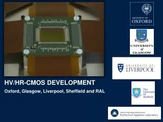
HV CMOS sensors based on 3D integration Wafer bonding TSV Readout chip Smart diode sensor Signal charge
Tezzaron-GF 3D Process • TezzaronGlobal Foundries process, offered by Mosis and CMP. • Two tier process based on Global Foundries 130nm technologies. • Two wafers (tier 1 and tier 2) are connected face to face with Cu-Cu thermo-compression bonding. • For this purpose Tezzaron uses the 1µm thick Cu TopMetal to create the “leopard skin” pattern. • The Super contacts (TSVs) are realized after the transistor processing and before the metallization – via middle process (TSV diameter of 1,2 µm, TSV distance 25 µm). • The top wafer is thinned to access the super contacts. Back side metal is added for bonding after thinning. Wafer to wafer bonding Bond interface layout One tier
3D HVCMOS in Tezzaron-GF Process Back Side Metal TSV Tier 1 (thinned wafer) M1 M2 M3 M4 M5 M1 M2 M3 M4 M5 M5 M4 M3 M2 M1 M5 M4 M3 M2 M1 Tier 2 SDA
Technology options • For the sensor part three options. • 1) Use the HV technology “BCD lite”. This technology includes the low-power option and the high-voltage option. • Substrate resistivity 20 Ωcm. • High voltage n-well available. • 35V reverse bias is achievable, leading to a depleted layer of about 5 µm. • 5 metal layers • Reticle size : 26 x 30 mm. • The engineering run cost ~ 350k$ • Upper tier thinned down.
Technology options • For the sensor part three options. • 2) Use 130nm LP process. • Lower substrate resistivity (?). • N-well diode breakdown voltage ~ 20V. • Avalanche multiplication process might be possible. PMOS NMOS NW LPW NW LPW DN DN PSUB
Avalanche Multiplication • LED – light pulses have been detected. • Signal amplitude has been measured as the time over threshold. • From 60V reverse bias, the time over threshold increases exponentially. (about 2x increase) Time overthreshold [μs] Measurement done by Ann-Kathrin Perrevoort 11 10 Charge multiplication! 9 8 7 6 5 20 40 60 80 0 Reverse bias [V]
Technology options • For the sensor part three options. • 3) Use 130nm GF process with a high resistivity wafer. • Wafer resistances 500 to 1000 Ω cm mightbepossible. PMOS NMOS NW LPW NW LPW DN DN PSUB
3D HVCMOS – readout architecture • 20um x 20um pixels, expected noise of 15 e • Time resolution of about 20 ns and a power consumption of 1-2 uW/pixel TS RO cell FIFO Address ToT TS Comparator Address ToT TS Address ToT TS Address ToT TS Trigger TSdel Pixels
3D HVCMOS – results and plans • Submission planned for spring 2013. • We have separately tested both components of the detector, the sensor part implemented in the AMS HV technology and the Tezzaron / GF 3D technology. • Sensor readout chip in Tezzaron/GF 3D process designed by Bonn and CCPM – nice results will be presented by Theresa Obermann. • HVCMOS in AMS H18 technology stand alone – tests and the readout with FEI4; will be presented by Daniel Münstermann. • The 3D integration of HVCMOS sensors should be straightforward.
Summary • The HV-CMOS technology allows production of a hybrid detectors in a commercial process without the need for dedicated sensors. In this way we are reducing of costs, time and complexity.
FETC4 FETC4 – prototype 3D IC • Part of a Multi Purpose Wafer produced at Tezzaron 3D and Chartered 130 nm CMOS (tested w.r.t. irradition) • Pitches 50 x 166 • Optimized technologies • The 2D tiers are fabricated on the same wafer Analog tier (14 columns x 61 rows) • Similar circuitry as FE-I4 Injection capacitances, CSA, Discriminator • For standalone testing the analog tier has a shift register implemented • For the vertical connection to the digital tier it has a TSV at the discriminator output Digital tier (14 columns x 62 rows) • Four pixel region layout • For standalone testing it has a shift register implemented • For the vertical connection to the analog tier it has a TSV at its input
FETC4 FETC4 – prototype 3D IC Circuitryof analog tier
FETC4 • The depleted layer is relatively small => relatively small signals. THRESHOLD NOISE Read analogtier Read digitaltier Read analogtierRead digital tier • Threshold ~2400 e Noise ~94 e • The threshold can be measured by reading out both tiers with the same result • The measured threshold and noise dispersions and mean values are within the expectations
HV2FEI4 • Pixel matrix: 60x24 pixels • Pixel size 33 m x 125 m • 21 IO pads at the lower side for CCPD operation • 40 strip-readout pads (100 m pitch) at the lower side and 22 IO pads at the upper side for strip-operation • Pixel contains charge sensitive amplifier, comparator and tune DAC. IO pads for strip operation Pixel matrix 4.4mm Strip pads IO padsfor CCPD operation
CCPD readout FEI4 Pixels Signal transmitted capacitively CCPD Pixels 2 2 Bias A 3 3 Bias B 1 1 Bias C
Irradiation with protons at KIT (1015neq/cm2, 300 MRad) -60V 0V -30V 22Na 55Fe
Publications • I. Peric, A novel monolithic pixelated particle detector implemented in high-voltage CMOS technology, Nucl. Instrum. Meth. A582 (2007) 876–885. • I. Peric, A novel monolithic pixel detector implemented in high-voltage CMOS technology, IEEE Nucl. Sci. Symposium Conference Record vol. 2 (2007) 1033–1039. • I. Peric, Ch. Takacs, Large monolithic particle pixel-detector in high voltage CMOS technology, Nucl. Instrum. Meth. A624 (2010) 504–508. • I. Peric, Ch. Takacs, J. Behr, P. Fischer, The first beam test of a monolithic particle pixel detector in high-voltage CMOSTechnology, Nucl.Instrum. Meth. A628 (2011) 287–291. • I. Peric, Ch. Takacs, J. Behr, P. Fischer, Particle pixel detectors in high voltage CMOS technology - new achievements, Nucl. Instrum. Meth. A650 (2011) 158–162. • I. Peric for HVCMOS Collaboration, Active Pixel Sensors in high voltage CMOS technologies for ATLAS, JINST 7 C08002 (2012). • I. Peric, Hybrid Pixel Particle Detector Without Bump Interconnection, IEEE Trans. Nucl. Sci. 56 (2009) 519–528. • I. Peric´, C. Kreidl, P. Fischer, Hybrid pixel detector based on capacitive chip to chip signal-transmission, Nucl. Instrum.Meth. A617 (2010) 576–581.
Experimental results - overview HVPixel1 – CMOS in-pixel electronics with hit detection Binary RO Pixel size 55x55μm Noise 60e MIP seed pixel signal 1800 e Time resolution 200ns Monolithic detector - frame readout Capacitive coupled hybrid detector • PM2 chip - frame mode readout • Pixel size 21x21μm • 4 PMOS pixel electronics • 128 on-chip ADCs • Noise: 21e (lab) - 44e (test beam) • MIP signal - cluster: 2000e/seed: 1200e • Test beam: Detection efficiency >98% • Seed Pixel SNR ~ 27 • Cluster signal/seed pixel noise ~ 47 • Spatial resolution ~ 3 m Monolithic detector – continuous readout with time measurement CCPD2 -capacitive coupled pixel detector Pixel size 50x50μm Noise 30-40e Time resolution 300ns MIP SNR 45-60 MuPixel – Monolithic pixel sensor for Mu3e experiment at PSI Charge sensitive amplifier in pixels Hit detection, zero suppression and time measurement at chip periphery Pixel size: 39x30 μm (test chip) (80 x 80 μm required later) MIP seed signal 1500e (expected) Noise: ~40 e(measured) Time resolution < 40ns Power consumption 7.5µW/pixel Irradiations of test pixels 60MRad – MIP SNR 22 at 10C (CCPD1) 1015neq MIP SNR 50 at 10C (CCPD2) HPixel - frame mode readout In-pixel CMOS electronics with CDS 128 on-chip ADCs Pixel size 25x25 μm Noise:60-100e (preliminary) MIP signal - cluster: 2100e/seed: 1000e (expected) HV2FEI4 chip CCPD for ATLAS pixel detector Readout with FEI4 chip Reduced pixel size: 33x125μm RO type: capacitive and strip like Noise: ~80e (stand alone test, preliminary) SDS - frame mode readout Pixel size 2.5x2.5 μm 4 PMOS electronics Noise: 20e (preliminary) MIP signal (~1000e - estimation) 1. Technology 350nm HV – substrate 20 cm uniform 2. Technology 180nm HV – substrate 10 cm uniform 3. Technology 65nm LV – substrate 10 cm/10 m epi