Download
1 / 30
300 likes | 383 Views
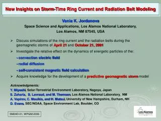
Radiation Belt Storm Probe Electric Field and Waves Instrument (EFW) PI: Prof. John Wygant, UMN jwygant@comcast.net , (612) 626-8921 PM: Dave Curtis, UCB dwc@ssl.berkeley.edu , 510-642-5998. Org Chart. Major Subcontracts. UMN will subcontract to UCB and LASP to develop the EFW instrument

E N D
Radiation Belt Storm Probe • Electric Field and Waves Instrument • (EFW) • PI: Prof. John Wygant, UMN • jwygant@comcast.net, (612) 626-8921 • PM: Dave Curtis, UCB • dwc@ssl.berkeley.edu, 510-642-5998
Major Subcontracts • UMN will subcontract to UCB and LASP to develop the EFW instrument • No other significant subcontracts are required. All hardware built and tested in house.
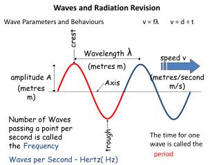
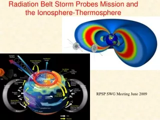
Science and Measurement Objectives (1) • Science Objective: Measure electric fields associated with a variety of mechanisms causing particle energization, scattering and transport in the inner magnetosphere. • These mechanisms include: • Energization by the large-scale convection E-field. • Energization by substorm injection fronts propagating in from the tail. • Radial diffusion of energetic particles mediated by ULF MHD waves. • Transport and energization by intense magnetosonic waves generated by interplanetary shock impacts upon the magnetosphere. • Coherent and Stochastic acceleration and scattering of particles by small-scale, large-amplitude plasma structures, turbulence and waves (EM and ES ion cyclotron waves, kinetic Alfven waves, solitary waves, electron phase space holes, zero freq. turbulence)
RBSP Electric Field Waves • Four spin plane booms (2 x 40 m and 2x 50 m) • Spherical sensors and preamplifiers near outboard tip of flexible cable boom (500 kHz response) • Flexible boom cable ~7-8 thin wires carrying power/bias commanding out to sensor electronics and signals back to SC. • Outer braid of cable is a conductor tied to SC chassis through large resistor (100 k ohms to 1 M ohms). • Two spin axis stacer booms (2x6 m) with outboard sensors • Sensors are current biased by instrument command to be within ~ 1 volt of ambient plasma potential. (except sensors at ends of E-field booms) • Main electronic box (filtering, sampling, A-D conversion, commanding, tm formatting, burst memory, spectra, IDPU etc. • Telemetered electric field quantities include: • SC- sensor potential (V1s, V2s, V3s, V4s, V5s, V6s) • Difference between opposing sensors (V12, V34, V56) • Electrostatic cleanliness spec designed to keep variations of potential across spacecraft surfaces smaller than 1 Volt. 4 SUN 6 2 1 5 3 SC Rotation
Mechanisms associated with energetic particle acceleration and transport (Mauk/APL)
E-Fields in the Active Radiation Belt CRRES measurements of the E-field during a pass through the the inner magnetosphere March 1991 Major Geomagnetic Storm MHD waves: an important mechanism for radially diffusing and energizing particles. The shock induced magnetosonic wave created a 5 order of magnitude increase in 13 MeV electron fluxes in <100 seconds resulting in a new radiation belt that lasted two years The large scale electric field produced a ~70 kV potential drop between L=2 & L-4 and injected ring current plasma. dDst/dt= - 40 nT/hr
Injection Front: prompt energization of ~ 1 MeV electrons near • R=4.28 Local midnight • Top panels • Ey gse, Bz gse • Drift Echo signature in energetic particles • Intense 100 mV/m • (ptp) electric field turbulence in Ey and Ez gse (0.2 to 10 Hz)
Science and Measurement Objectives (3) • Key Measurement Quantities: • Spin plane component of E at DC-12 Hz (0.05 mV/m accuracy). • Spin axis component of E at DC-12 Hz (~3 mV/m accuracy). • E- and B-field spectra for nearly-parallel and nearly-perpendicular to B components between 1 Hz and 12 kHz at 6-s cadence. • Spacecraft potential estimate covering cold plasma densities of 0.1 to ~100 cm-3 at 1-s cadence. • Burst recordings of high-frequency E- and B-field waveforms, as well as individual sensor potentials for interferometric analyses.
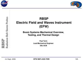
Boom Accommodation Schematic Diagram of EFW
Spin Plane Boom (SPB) Example of SPB, Cable, Preamp, Fine Wire and Sphere (THEMIS Flight Model) • Mass: 2.2 kg/unit (4 total). • Envelope: 9.9”H x 4.6”W x 8.6”D. • Deployed Length: 80/100 m tip-to-tip. • 47 m cable + 3 m fine wire in each SPB. • Deploy Rate: 0.5-1.0 cm/s. • Cable Mass Rate: ~3 g/m. • Fine Wire Mass Rate: < 1 g/m. • Preamp Mass: 48 g (up to 150 g w/up-shield and cable driver). • Sphere/Keyreel Mass: 100 g. • Deployed spin MOI: 600 or 360 kg-m2/boom (100-g preamp); 1920 kg-m2 total. • Power: 2.6 W/unit (typ., deploy motor only). • Actuators: Doors are spring-loaded, SMA or FrangiBolt-released; Cable deploy is motor-driven; no pyros required for actuation. RBSP-EFW: SPB Packaging Concept (THEMIS)
Axial Boom (AXB) Examples of AXB, Tube, and Preamp/Whip (THEMIS Flight Models): • Mass: 4 kg total (2 booms + tube). • Footprint: 41H x 5 to 6 OD inches. • Deployed Length: • 12m tip-to-tip. • 1-m whip sensor stacer. • Power: 35 W max for 1-2 s, per boom (deploy only). • Actuators: deploy is spring-driven, Frangibolt-released; no pyros required for deploy.
Instrument Data Processing Unit (IDPU) • Mass: 4.7 kg. • Dimensions: 9.75H x 4.7W x 7.95D inches (add 2-inch keepout for connectors to depth). • Power: 7.5 W (primary side, CBE). • Elements and Function: • Chassis – provides structural integrity and radiation shielding (7-mm Al equiv.). • Backplane – signal and power distribution. • Low-Voltage Power Supply (LVPS) and Power Controller Board (PCB) – power conversion, regulation, and switching. • Data Processing Unit (DPU) and Memory (SSR) – instrument control; data storage, routing, and compression. • Boom Electronics Board (BEB) – sensor and bias surface control. • Digital Signal Processing Board (DSP) – analog signal conditioning, ADC, digital waveform filtering, on-board spectral product calculation. • UIowa (EMFISIS) Interface Board (UII) – buffering of E-field signals to EMFISIS; buffering of B-field signals from EMFISIS; burst coordination signals; etc. (may be part of DSP or BEB).
Digital Signal Processor (DSP) • The DSP board provides analog conditioning of the signals from the E- and B-field sensors on RBSP, analog-to-digital conversion of those signals at 16-bit resolution, digital waveform filtering, and on-board FFT-based spectral product computations (auto- and cross-spectra). • All analog signals (V1-V6, E12, E34, E56 (both DC- and AC-coupled) and SCM1-3) are sampled at a constant 32-ksamp/s rate through the analog mulitplexer and switch system, and the three 256-ksamp/s ADCs. • The 3 ADCs can be reconfigured so as to maintain sampling at lower base rates if one or two fail during the mission. • Independent Survey and Burst digital filter chains provide anti-aliased and down-sampled waveform data at power-of-two intervals from 32 ksamp/s to 1 samp/s. • Broadband power-of-two Filter Bank channels are derived directly from the digital filter chain outputs for use in on-board triggering or Survey science output. • DC B-field data (EMFISIS fluxgate) used to rotate AC E- and B-Field into field-aligned coordinate system for input to on-board FFT-based spectral processing. • On-Board FFT-based spectral processing of AC E- and B-Field data used to produce auto- and cross-spectral data products.
Technical Readiness • Boom Deployment Systems • TRL 8, based on ISEE, CRRES, Polar, FAST, Cluster-II, and THEMIS heritage. • Changes will include thinner cable, different accommodating SC. • Sensor Electronics (Preamp and BEB) • TRL 8, based on Polar, Cluster-II, and THEMIS heritage. • Changes will include thinner cable, possible cable driver. • IDPU Power, DSP, DPU, and Burst Memory • TRL 7-8, based on Polar, FAST and THEMIS heritage. • Changes will include interfaces to other instruments and SC, adjustments to filter frequencies and ADC rates, flight software changes.
Concept Risks • New SPB cable design • A new, smaller harness design was proposed for RBSP • Electrical and Mechanical tests under way to verify the new design meets requirements and reliability • Mass and volume implications if it can’t be used • Parts • Heritage electronics design from THEMIS uses Grade 3 parts • Some parts may fail up-screening to Level 2, requiring a redesign • Start parts screening early in Phase B
System-Level Issues • Spin-Axis Pointing • Impact of different illumination on DC and AC systematic errors (EFW and EMFISIS). • Axial Boom Accommodation and SC Stability • Dual Axial booms to be accommodated along central axis of RBSP SC. • Potential for solar array shadowing issues • AXB effects on RF Antenna pattern (in work) • Well-known and understood issues of dynamic stability (spin/transverse MOI requirements).
Phase A Activities • Develop Management Plan (Organization, Cost, Schedule, etc.). • Participate in Requirements definition and flow-down efforts. • Participate in Spin Axis Pointing trade study. • Participate in Spacecraft Accommodation Studies, including: • Ongoing Axial boom trades: Telecom antenna issue, Offpointing • SC charging and ESC specification. • C&DH system interface • Boom mounting and dynamics • Thermal interface • Perform EFW Design Trade Studies, including: • Choose custom Gore cable for SPBs (mass vs. electrical response). • Define EFW frequency response and noise level requirements (joint with EMFISIS). • Choose processor for DPU (8085 or FPGA-based). • Choose preamp floating supply range (100 vs. 200 volts). • Define capabilities of on-board Burst and Spectral Product systems. • Define EFW-EMFISIS interface.
Integration and Test Plan (1) • Instrument Level I&T (occurs at UCB): • Preamp Thermal Qualification and Acceptance Test: • Performed informally on previous missions (Polar, Cluster, FAST), and formally as part of parts qualification on THEMIS. • Preamps generate little internal heat, and are either isolated from SC heat sources (SPB), or attached to efficient radiators (AXB). • Thus, preamp enclosure and PWB exposed to relatively extreme temperature swings during eclipse: • THEMIS Tmin of -135 C for 3-hour eclipse. • 1 C/min rate of cooling. • Batch of complete ETUs (8 on THEMIS) run through >=7 hot-cold cycles to verify design meets or exceeds performance requirements. • Each Flight Preamp run through >=7 hot-cold cycles to verify that the unit meets or exceeds performance requirements.
Integration and Test Plan (2) • Instrument Level I&T, con’t (occurs at UCB): • Boom Unit (SPB, AXB) Vibe, Functional and TVAC Testing: • Vibe tests as per GEVS requirements: • Levels as per launch vehicle environment and SC modeling. • Tests performed in Bay Area (Quanta Labs, for example). • Performance Tests (Science and Engineering). • Performed at Ambient; Hot and Cold TVAC. • Limited DC and AC Functional Tests (gain, offset, phase at DC and selected frequencies). • Mechanical and actuator performance: • Motor, SMA, or frangiBolt current at min, max, and nominal supply voltages. • Deployed length measurement and length indicator calibration. • Run-out (straightness) and 1st-mode estimation (AXB only).
Integration and Test Plan (3) • Instrument Level I&T, con’t. (occurs at UCB): • Sensor and Boom Electronics Board (BEB) Calibration (Science Cal, or SciCal). • Detailed calibration of Sensor and BEB operation and verification of required performance. • Instrument transfer function vs. frequency (gain, phase, offset). • Bias current and voltage frequency response and offset control calibration. • Noise levels. • IDPU Functional, Vibe and TVAC Testing: • Electrical Performance Tests. • Commanding and Instrument Modes Tests. • U.Iowa Interface Board (UII) Testing. • Boom Deploy Testing (Simulated and Actual). • Power control and consumption. • Software control of SPB boom deploy.
Integration and Test Plan (4) • Suite and SC level I&T: • Fields Phasing and Timing Test: • Establishes relative phase and/or time delay between EFW and EMFISIS fields channels. • Electrostatic Cleanliness verification: • All instruments and spacecraft subsystems. • Functional Tests: • Commanding: • Instrument Modes (Survey, Burst, Common Burst, etc.). • Instrument Commissioning and Boom Deploy. • TM Playback. • Compatibility: • conducted and radiated EMI/EMC. • commanding and functionality (“playing well with other instruments and the spacecraft”). • Note that significant “self-test” capability exists in current design; ie. Minimal GSE required for performance testing at Suite and SC level.
Mission Operations Concept • Boom deployment during commissioning requires real time commanding and close coordination with the spacecraft • Once in nominal operations, only periodic internal calibrations and occasional mode changes as we pass into different environments are required • No significant command bandwidth required • Need the ability to send up time-tagged commands (like STEREO). • Calibration mode will effect data provided to EMPFISIS and may also charge the spacecraft which would impact low energy particle measurements. • Operations will be run from a UCB SOC • same facility used for FAST, HESSI, CHIPS, STEREO, THEMIS
Unique Requirements • SC Charging and Electrostatic Cleanliness (ESC) • SC potential symmetrization, in addition to charging control. • All exposed surfaces sufficiently conducting and tied together electrically. • See THEMIS ESC Specification for example of implementation and verification plan. • Spin Axis Pointing • RBSP spin axis shall be oriented to ensure illumination of the two EFW axial sensors. • RBSP spin axis shall be oriented to ensure limited shadowing of the four EFW spin plane sensors. • Velocity and B-Field Accuracy • Determination of spacecraft vector velocity and local vector B-field must be such that the -VxB E-field estimate is accurate to 0.1 mV/m above 2 (TBR) Re altitude.