Download
1 / 25
290 likes | 491 Views
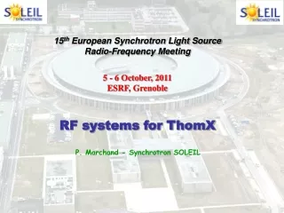
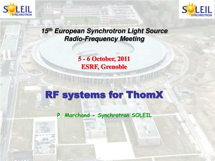
15 th European Synchrotron Light Source Radio-Frequency Meeting 5 - 6 October, 2011 ESRF, Grenoble RF systems for ThomX. P. Marchand - Synchrotron SOLEIL. The ThomX Project. Compact source of hard X-rays (40 – 90 keV)

E N D
15th European Synchrotron Light Source Radio-Frequency Meeting 5 - 6 October, 2011 ESRF, Grenoble RF systems for ThomX P. Marchand - Synchrotron SOLEIL
The ThomX Project Compact source of hard X-rays (40 – 90 keV) Flux of up 1013 photons / sec, generated by Compton Back Scattering (CBS : collisions between e- bunches and laser pulses ωdif ~ 4γ2ωlaser) - Medical sciences (imaging + therapy) - Cultural heritage sciences (Louvre Museum, for instance) Applications Compactness for accommodation in hospitals and museums Funding of 12 M€ for Phase 1 : building of a prototype feasibility proof Phase 2 : industrialization Work supported by the EQUIPEX program from the Research Ministry, Région Ile de France, CNRS-IN2P3 and University of Paris-Sud Contributions from LAL-Orsay CNRS-IN2P3, SOLEIL, CELIA Bordeaux, ESRF, C2RMF-CNRS, UDIL CNRS, INSERM Grenoble, Thales TED, Institute Neel Grenoble LAL-Orsay & SOLEIL in charge of the accelerator complex, housed inside the former DCI building on the university site in Orsay (~ 5 km from SOLEIL)
ThomX accelerator complex SR optics : 4-fold symmetry Double Bend Achromat FP optical cavity Interaction Region 7 m 10 m Injection of a single e- bunch (20 mA), which collides at each turn with laser pulses at the IP, inside the FP optical resonator X rays from CBS CBS fast degradation of the e- beam quality storage for ~ 20 ms Injection rate of 50 Hz (after 20 ms, extraction to BD & new injection)
The LINAC Injector 2.5 cell 3 GHz gun • Photocathode RF gun : • Replica of the CERN-CTF3 gun, built by LAL • Ec = 100 MV/m with 10 MW • Mg cathode (Q up to 1 nC) • Laser : l = 266 nm, E ~ 100 µJ, st ~ 5 ps • Accelerating structure : • LIL type (4.5 m long) AS, spare from SOLEIL • P = 10 (20) MW E = 50 (70) MeV • RF Power source : • 35 MW TH 2100 klystron from Thales • Solid state modulator (3 µs, 50 Hz) • Power splitting : 10 MW Gun • 20 MW AS • Expected beam performance (PARMELA) • E ~ 50 MeV (max 70) • sE/E < 0.4 % • en ~ 5 p mm.mrad HV modulator Klystron
Selected RF frequency 500 MHz Good compromise • VRF = 500 kV 1 single cell cavity PRF (dis) ~ 35 kW • Availability of power sources & other RF components • Reasonable equipment size • Zhom will dictate the choice of cavity design SR RF parameters • At 50 MeV, DUrad ~ 2 eV / turn Pbeam ( Ib = 20 mA ) ~ 0 • No power to be delivered to the beam (s = 0) • RF system only generates VRF for suitable longit. acceptance
HOM impedances and instability thresholds DU rad ~ 0 t damping ( ~ 1 s ) >> t storage ( ~ 20 ms ) To preserve the beam quality Instability growth time, ti > 20 ms Longitudinal HOM in resonance, til = 2 Qs E/e / (a IoRsfm) Rs . fm (HOM) natural : 0.1 - 1 M . GHz til ~ 10 µs !! Transverse HOM in resonance, tit = 2 E/e / (bTfrevIoRT) RT (HOM) natural : 1 - 10 M / m tit ~ 10 µs !! In both, longitudinal and transverse cases, damping of Zhom by a few 103 is required !! (more critical than in 3rd generation LS x 10)
Cures to HOM impedances 1) De-Qing of the HOM (HOM couplers) a few 102 - 103 Not enough & cumbersome equipment around the cavity PEP-2 cavity (LBNL) « DAMPY » cavity - ALBA
Cures to HOM impedances 2) HOM tuning Prevent resonant excitation by the beam • ELETTRA cavity with its 3 tuning means • - Temperature control of fHOM • - DLcav (mech. deformation) Dfo • - Movable plunger on the equator Power coupler Tw ± 0.1°C DLcav • 1 single cavity • ~ No beam loading • Small circumference Well suited to HOM tuning • Beam spectrum lines : df = 18 MHz • HOM resonance BW : a few 10 kHz • DfHOM (tuning) : a few MHz • Rs (Df = 0) / Rs (Df ) = 1 + (2 Q Df/f )2 • A few 103 to 104 Ok for ThomX Plunger
l = 20 ms HOM Spectrum Ok Ok Ok Ok Ok ELETTRA cavity L-HOM spectrum (9 modes) over the 18 MHz base band
RF power source VRF = 500 kV, using 1 ELETTRA cavity PRF (dis) = 35 kW At 500 MHz Klystrons, IOTs, Solid State Amplifiers (SSA) SOLEIL technology - Well proven (6 years op.) - No HV - Modularity redundancy - … 35 kW SSA of the SOLEIL Booster 147 modules of 330 W @ 352 MHz ~ 35 000 runing hours over 6 years Operational availability of 100 % Minor pbs on 5 modules only without impact on the operation H = 2.50 m, = 2 m For ThomX, make it at 500 MHz
SOLEIL - LNLS collaboration Two amplifiers of50 kW @ 476 MHz for the LNLS storage ring with components designed by SOLEIL (RF modules of 400 W) April 2010 : the SOLEIL-LNLS team in Campinas-Brazil, after successful tests of the amplifiers
LNLS 50 kW RF plants The two 50 kW SSA have run satisfactorily on the LNLS SR for ~ 1 year
SOLEIL R&D’s with SSA @ 352 MHz • 6th generation transistors (Vdc = 50 V) + SOLEIL expertise fast progress • At352 MHz,Pmod ~ 700 W, G > 20 dB, > 70% • [CurrentLR301mod. (Vdc=28 V) : P = 315W, G = 13dB, = 62% @ 352 MHz] • Huge improvement : Pmod x 2.2 , better performance (G , , linearity) • & thermal stress strongly reduced (DT : - 60 °C) longer lifetime • Beg. 2009, transfer of technology agreement concluded with ELTA-AREVA • ESRF contract for 7 SOLEIL type amplifiers of 150 kW (14 x 75 kWtowers) • June 2010 : A 10 kW unit (16 modules) successfully tested at SOLEIL • June 2011 : First 75 kW tower passed the acceptance tests ( ESRF) SOLEIL SSA : Evaluate 6th generation transistors of lower power (~ 330 W) from NXP & Freescale replace LR301 with min. modification • In view of storing 500 mA using a single cryomodule : • Combination of two 180 kW SSA for powering one cavity • Input power coupler (P > 300 kW) developt CERN/ESRF/SOLEIL collab.
R & D’s with SSA @ frequencies other than 352 MHz • Prototypes of 500 MHz module: P = 650 W, G = 18 dB, η = 67 % • 1 x 50 kW for ThomX • 4 x 150 kW for SESAME Components design is completed First tower : by the end of 2012 • Extend the technology to frequencies from FM to L band • VALVO/SOLEIL set of circulators covering the whole freq. range • Prototype of 88 MHz module : P = 900 W, G = 25 dB, η ~ 80 % • BBEF : 20 kW CW – 1.3 GHz SSA for the Beijing University • Collab. Agreement under finalization with CERN for a prototype of • 20 kW @ 200 MHz in anticipation of 2 x 1.6 MW • New features : • Modular high efficiency 230 V_ac / 50 V_dc power converters • Option for housing the complete SSA inside a cabinet • Waveguide-to-coaxial combiner (WaCCo) adjustable coupling • Possibility of matching variable number of modules
Waveguide-to-Coaxial Combiner (WaCCo) 2 coaxial inputs dl WG output • Two 6 inches coaxial input ports (2 x 80 kW) 1 WG output • Replace a coaxial combiner + a coaxial-to-WG transition • Design optimization with HFSS and Microwave Studio • A 500 MHz prototype is being fabricated by BBEF • Movable SC can ensure a good matching for different configurations wit diff nb of dissipaters per tower or diff nb of modules per dissipater
Phase loop Frequency tuning loop Amplitude loop RF SWITCH 40 kW AMPLIFIER Coupler 3dB Drive CAVITY Tuner 500 MHz Tuning control RF ON/OFF PID PID in dV Phase control Fo dF PID df cav - + Voltage control Vcav Fcav ThomX LLRF system – slow loops Compensation of slow perturbations >> tfcav = 40 µs Conventional LLRF (frequency, phase, amplitude loops) Replica of the actual analogue SOLEIL design, adapted for 500 MHz
Fast phase / energy oscillations • Injection errors, dEi, di • Mismatch between injected bunch and RF bucket • HOM excitations • Transient beam loading • (Ib: 0 - 20 mA instantly) -d = 8° ( divided by Gfbk ) -Only first injections (stationary after ~ 1s) dE/E dEi Oscillations in phase & energy @ fs, the synchrotron frequency with damping time, td 1/DUrad di d(t) t di d Either Phase or Energy errors Phase & Energy oscillations (quadrature)
Fast phase / energy oscillations e- bunch length : 20 – 30 ps rms Laser pulse duration : 5 ps rms Synchro e- / laser Dt < 5 ps D < 1° Still amplified by mismatch & HOM (DE/E)inj = 0.5 % (LINAC) Dinj = 8° (AS) Without oscillation damping: Emittance growth Bad bunch / laser overlap Loss of efficiency in the e-/laser interactions @ IP • td ~ 1 s >> tst = 20 ms ~ no natural damping during tst • fs = 500 kHz >> BWcav = 25 kHz damping through the cav. impossible 3 means for generating some damping : 1) Longitudinal FB using an additional broad band cavity 2) Harmoniccavity Landau damping 3) Direct RF FB on the main cavity increase its effective BW (> 500 kHz) No need for additional cavity
Direct RF Feedback principle G Z(ω) C - Pin Ib Ig Rg Rs Vc + L With FB : ; Loop delay At resonance ( r) , Gain limitation ( stability criterion ) Ampli-cav distance ThomX : ampli - cavity distance ~ 10 m DT ~ 150 ns Glimit ~ 60 BW ~ 1.5 MHz >> fs
Cavity transfer function with RF FB DT = 150 ns fr - fs fr + fs Frequency (MHz) DT = 150 ns Frequency (MHz)
RF FB + fast beam phase loop BPM d Phase comparator G Ib 90° MO 500 MHz AMPLI 50 kW RFSwitch Driver 3 dB CAVITY Phase Shifter Interlocks PUcav RF feedback RF FB BWcavx (1+Go) > fs ModulateVcavat f > fs Go Att - Phase comparison between Vc (PU cav) & Ib (BPM) - The error signal, d (+ 90°) controls a phase shifter Alternative : Modulate the MO with d Phase loop (BW > fs) BW ?
Phase / energy oscillations with RF FB + fast phase loop Dinj = 10°, Go = 50, G = 5 , DT = 150 ns Damped after 20 µs T_damping = 3 µs for G = 30 (stability limit)
3dB Direct RF Feedback Go Complete LLRF A Att Tuner 50 kW AMPLI RF SWITCH MO 500 MHz Coupler 3dB PA CAVITY Tuning control PID PID Beam PU Att Phase control Beam phase PID G Conventional system with 3 « slow » loops around the cavity + - Voltage control Frequency Amplitude Phase Oscillations @ fs (500 kHz) inj , HOM, … - Direct RF Feedback (G ~ 50) - Fast beam phase loop (BW > 500 kHz)
Summary & Conclusion RF system of ThomX SR 1) One 500 MHz ELETTRA type cavity (HOM tuning) 2) 500 kV with 35 kW, supplied by a SOLEIL type SSA 3) LLRF : conventional system with 3 slow loops (fr, V, v) + high gain RF feedback & fast phase loop (b) Rem : ThomX is a small machine, but quite complex and challenging, in particular as regards to the electron beam dynamics Planning : RF equipment available for installation in ThomX by mid-2013 - Amplifier & LLRF designed & supplied « turn key » by SOLEIL - Cavity one of the ELETTRA cavities, dedicated to SESAME, made available for ThomX until mid-2016 (validation on the machine and then fabrication of another one, modified or not)