Download
1 / 39
440 likes | 671 Views
NEWBuildS Tall Wood Building Design Project – Seismic & Gravity Load Analysis and Design. Zhiyong Chen University of New Brunswick. www.NEWBuildSCanada.ca. 1. Introduction. 1.1 Customer Demands & Challenges on Structures. Taller Buildings Structural systems: Ductile

E N D
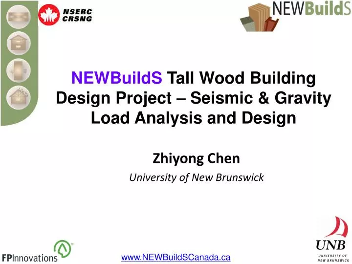
NEWBuildS Tall Wood Building Design Project – Seismic & Gravity Load Analysis and Design Zhiyong Chen University of New Brunswick www.NEWBuildSCanada.ca
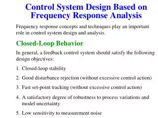
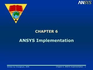
1.1 Customer Demands & Challenges on Structures Taller Buildings Structural systems: Ductile Connection systems: High strength & Ductile Larger Open Space Floor systems: Long span & Vibration We are trying to address these issues !!!
1.2 Flow Diagram Site & Loads (Dead, Live, Wind, Snow and Seismic) Material, Structural Assembles & Connections Structural System Checking on Structural & Fire Issues using FEA [No] 1~3 Iterations [Yes] Structural Sketch & Report Suitable Structural Assembles & Connections
2.1 Concept Design Structural System Post-beam system Shear wall system Shear wall + core system Shear Wall Construction Platform framing: Easy to be built storey by storey Balloon framing: Reduce the storey joints - Possible storey number +
2.1 Concept Design Stiffness, Strength & Ductility (1) Steel Beam Core Shear Wall Vertical Joints (Dowel Type) (2) (3) Hold-Down Shear Connector (3)
2.2 Lateral Load Resisting System Hold-Down The typical storey Shear Connector HSK System (Wood-Steel-Composite) LLRS
2.3 Gravity Load Resisting System The typical storey Beams are divided by column / wall GLRS
2.3 Gravity Load Resisting System Floor The typical storey GLRS
2.3 Gravity Load Resisting System Roof The typical storey GLRS
2.5 Sketch List GENERAL G-01: PROJECT DECRIPTION AND SKETCH LIST STRUCTURAL S-01: STRUCTURAL SYSTEM DESCRIPTION S-02: TYPICAL FRAMING PLAN S-03: TYPICAL BUILDING SECTIONS S-04: TYPICAL DETAILS S-05: TYPICAL DETAILS S-06: CONSTRUCTION SEQUENCE DIAGRAMS
3.1 Massive-Timber-Panel Moment Frame (1) Steel Beam (2) Vertical Joints (3) Hold-Down (3) Shear Connector MTPMF
3.1.1 Influence of Hold-Down Deformation Hysteresis loops The ductility of the hold-down affects the system ductility.
3.1.2 Influence of Steel Beam Deformation Load-deformation curve Steel beam increases the system stiffness and ductility.
3.1.3 Influence of Vertical Joint Deformation Load-deformation curve Vertical joint affects the performance of the system.
(1) Stiffness of Vertical Joint (1) The ratio system stiffness increases with increasing the stiffness of the vertical joint. (2) For a denser fastening case, the system derives a higher stiffness in the rigid case.
(2) Strength of Vertical Joint (1) The curves of the two extreme cases form the boundaries of the other intermediate strength cases. (2) The first turning point of the curves from the infinite-connections-strength to zero-connection-strength cases increases with increasing the connection strength.
(3) Ductility of Vertical Joint - Static The first yield point increases with increasing ductility ratio of the connection.
(4) Ductility of Vertical Joint - Cyclic The system ductility and energy dissipation ability are improved by the ductile connections.
3.2 FEA Model of Tall Wood Building Geometrical Model and Elements LSL core, shear wall & diaphragm Shell element – S4R Steel & glulam beams, columns Beam element – B31 Material Models Timber – Elastic Steel – Ideal Elastic-Plastic Stress Stress Strain Strain
3.2 FEA Model of Tall Wood Building Connection Models Vertical joint & shear connector – Ideal Elastic-Plastic with ductility Hold-down connection – Ideal Elastic-Plastic with ductility under tension & without movement under compression Force Force Deformation Deformation
3.2 FEA Model of Tall Wood Building Connection Models Steel beam & GL column – Rigid connections GL beam to beam, column, wall & diaphragm – Hinge connections Contact Models Steel beam to Wall – Tie Panel to panel – Frictionless (in tangential direction) – Hard contact (in tangential direction) Stress Strain
3.2 FEA Model of Tall Wood Building Numerical Simulation Problem 3-Dimentional Non-linear Problem Size Number of elements is 90,834 Number of nodes is 154,592 Total number of variables 585,762 (Degrees of freedom plus any Lagrange multiplier variables) It is a huge & complex computational task with convergent problems
3.3 Frequency Analysis Sub-Space Method In X (E-W) direction In Y (N-S) direction In Z (rotation) direction
3.3 Frequency Analysis Influence of joint stiffness Semi-rigid FEA should be used, else the periods of the building would be under-estimated. The fundamental period of this building with semi-rigid joints in the East-West direction is close to that estimated by NBCC.
3.3 Frequency Analysis (L=37.3+30.6=67.3m) 1.66S (1) Wind would control the structural design in the North-South direction, while seismic would control it in the East-West direction. (L=60.5m) 0.94S 1.46S (2) Some external walls at axis 1 & 7 should be considered to address the torsional issue and the stiffness in N-S direction.
3.4 Gravity Loading Analysis In Y (N-S)direction In X (E-W)direction The differential shortening is not significant.
Risk method 3.5 Pushover Analysis In Y (N-S)direction In X (E-W)direction
Seismic response of the high-rise wood building is crucial in the ultimate limit state. Investigation method: Nonlinear time history analysis 22 “Far-Field” earthquake records will be scaled at the corresponding fundamental period of the building model to match the spectral acceleration, Sa, of the Vancouver design spectrum. 3.6 Seismic Analysis
Thank you! Yingxian Wood Pagoda (67.31m) Tall Wood Building (66m)