Download
1 / 60
800 likes | 1.91k Views
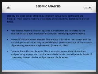
Seismic Analysis and Design Of Structures Using Response Spectra Or Time History Motions BY Ed Wilson Professor Emeritus of Civil Engineering University of California, Berkeley February 24, 2010. SUMMARY OF PRESENTATION On Advanced Numerical Modeling and Analytical Techniques

E N D
Seismic Analysis and Design Of Structures Using Response Spectra Or Time History Motions BY Ed Wilson Professor Emeritus of Civil Engineering University of California, Berkeley February 24, 2010
SUMMARY OF PRESENTATION • On Advanced Numerical Modeling and Analytical Techniques • Personal Remarks – 50 years experience of dynamic analysis • Seismic Analysis Using Response Spectra – CQC3 • Comparison with Direct Time History Dynamic Analysis • Retrofit of the San Mateo Bridge_- • The Fast Non-Linear Analysis Method – FNA Method • Retrofit of the Richmond San Rafael Bridge • Near Fault Seismic Analysis • Concluding Remarks
NINETEEN SIXTIES IN BERKELEY 1. Cold War - Blast Analysis 2. Earthquake Engineering Research 3. State And Federal Freeway System 4. Manned Space Program 5. Offshore Drilling 6. Nuclear Reactors And Cooling Towers
NINETEEN SIXTIES IN BERKELEY 1. Period Of Very High Productivity 2. No Formal Research Institute 3. Free Exchange Of Information – Gave programs to profession prior to publication 4. Worked Closely With Mathematics Group 5. Students Were Very Successful
DYNAMIC ANALYSIS USING RESPONSE SPECTRUM SEISMICLOADING Before the Existence of Inexpensive Personal Computers, the Response Spectrum Method was the Standard Approach for Linear Seismic Analysis
Figure 15.1a Typical Earthquake Ground Acceleration - Percent of Gravity
Figure 15.1b Absolute Earthquake Ground Displacements - Inches
Figure 15.2b Pseudo-Acceleration Spectrum, - Percent of Gravity Figure 15.2a Relative Displacement Spectrum y (T)MAX Inches
Major Approximation The loads are applied directly to the structure; whereas, the real earthquake displacements are applied at the foundation of the real structure.
Development of the Three Spectrum In Addition, All Spectrum Values Are Maximum Peak Values The Time History Details of the Duration of the Earthquake Have Been Lost
Three-Dimensional Spectra Analyses Equal Spectrum from any direction – CQC3 Method Maximum Peak Column Moments - Symmetrical All Values are Positive
Three-Dimensional Spectra Analyses 100/30 Spectrum Method Maximum Peak Column Moments - Not Symmetrical All Values are Positive
Summary of Multi-Component Combination Rules • The 100/30 and 100/40 percent rules have no theoretical basis. • The SRSS combination rule, applied to equal spectra, produces identical results for all reference systems and requires only one analysis to produce all design forces and displacements.
The CQC3 method should be used where the horizontal orthogonal components of the seismic input are not equal. • In case of the seismic analysis of structures near a fault, the fault normal and parallel motions are not equal.
In 1996 The CQC3 was Proposed by Professor Armen Der Kiureghian As a Replacement for the 30%, 40% & SRSS Rules For Multi-Component Seismic Analysis
Design Checks of Three-Dimensional Frame Members for Seismic Forces In order to stratify various building codes, every one-dimensional compression member within a structure must satisfy the following Demand/Capacity Ratio at all points in time: t = 0 = Static Loads Only
Where the forces acting on the frame element cross-section at time “t” are including the static forces prior to the application of the dynamic loads. The empirical constants are code and material dependent and are normally defined as .
Design Checks of Three-Dimensional Frame Members for Spectra Forces For the case maximum peak spectra forces, compression members within a structure must satisfy the following Demand/Capacity Ratio Where P(max), M2(max) and M3(max)have been Calculated by the CQC Method
The Retrofit of the San Mateo Bridge Demand/Capacity Ratios were calculated using COC forces using spectrum calculated from several three-dimensional sets of earthquake motions. Time-dependent Demand/Capacity Ratioswere calculated directly from the same set of earthquake motions. In general, the time-dependent Demand/Capacity Ratioswere approximately 50 percentof the ratios using the CQC forces.
Limitations of Response Spectrum Analysis • All forces and displacements obtained from a Response Spectrum Analysis are Maximum Peak Values and are all positive numbers. • The specific time the Maximum Peak Values occur is different for every period. • Nonlinear Behavior CANNOT be considered in a Response Spectrum Analysis. • Except for a single degree of freedom, a Response Spectrum Analysis is an APPROXIMATE METHOD • This is not Performance Based Design
S A P STRUCTURAL ANALYSIS PROGRAM ALSO A PERSON “ Who Is Easily Deceived Or Fooled” “ Who Unquestioningly Serves Another”
From The Foreword Of The First SAP Manual "The slang name S A P was selected to remind the user that this program, like all programs, lacks intelligence. It is the responsibility of the engineer to idealize the structure correctly and assume responsibility for the results.” Ed Wilson 1970
The SAP Series of Programs 1969 - 70 SAP Used Static Loads to Generate Ritz Vectors 1971 - 72 Solid-Sap Rewritten by Ed Wilson 1972 -73 SAP IV Subspace Iteration – Dr.Jűgen Bathe 1973 – 74 NON SAP New Program – The Start of ADINA 1979 Lost All Research and Development Funding 1979 – 80 SAP 80 New Linear Program for Personal Computers 1983 – 1987 SAP 80 CSI added Pre and Post Processing 1987 - 1990 SAP 90 Significant Modification and Documentation 1997 – Present SAP 2000 Nonlinear Elements – More Options – With Windows Interface
FIELD MEASUREMENTS REQUIRED TO VERIFY 1. MODELING ASSUMPTIONS 2. SOIL-STRUCTURE MODEL 3. COMPUTER PROGRAM 4. COMPUTER USER
CHECK OF RIGID DIAPHRAGM APPROXIMATION MECHANICAL VIBRATION DEVICES
FIELD MEASUREMENTS OF PERIODS AND MODE SHAPES MODE TFIELD TANALYSIS Diff. - % 1 1.77 Sec. 1.78 Sec. 0.5 2 1.69 1.68 0.6 3 1.68 1.68 0.0 4 0.60 0.61 0.9 5 0.60 0.61 0.9 6 0.59 0.59 0.8 7 0.32 0.32 0.2 - - - - 11 0.23 0.32 2.3
FIRST DIAPHRAGM MODE SHAPE 15 th Period TFIELD = 0.16 Sec.
The Fast Nonlinear Analysis Method The FNA Method was Named in 1996 Designed for the Dynamic Analysis of Structures with a Limited Number of Predefined Nonlinear Elements
BASE ISOLATION Isolators
BUILDING IMPACT ANALYSIS
FRICTION DEVICE CONCENTRATED DAMPER NONLINEAR ELEMENT
GAP ELEMENT BRIDGE DECK ABUTMENT TENSION ONLY ELEMENT
P L A S T I C H I N G E S 2 ROTATIONAL DOF Degrading Stiffness Elements are in SAP 2000
Mechanical Damper F = ku F = f (u,v,umax ) F = C vN Mathematical Model
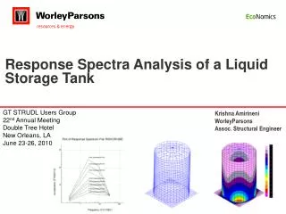
First Application of the FNA Method - 1994 103 FEET DIAMETER - 100 FEET HEIGHT NONLINEAR DIAGONALS BASE ISOLATION Nonlinear Seismic Analysis of ELEVATED WATER STORAGE TANK
92 NODES 103 ELASTIC FRAME ELEMENTS 56 NONLINEAR DIAGONAL ELEMENTS 600 TIME STEPS @ 0.02 Seconds COMPUTER MODEL
COMPUTER TIME REQUIREMENTS PROGRAM ( 4300 Minutes ) ANSYS INTEL 486 3 Days ANSYS CRAY 3 Hours ( 180 Minutes ) 2 Minutes SADSAP INTEL 486 ( B Array was 56 x 20 )
EXAMPLE OF FRAME WITH UPLIFTING ALLOWED UPLIFTING ALLOWED
Four Static Load Conditions Are Used To Start The Generation of LDR Vectors EQ DL Left Right
Confirmed by Shaking Table Tests By Ray Clough on Three Story Frame
Advantages Of The FNA Method 1. The Method Can Be Used For Both Static And Dynamic Nonlinear Analyses 2. The Method Is Very Efficient And Requires A Small Amount Of Additional Computer Time As Compared To Linear Analysis 2. The Method Can Easily Be Incorporated Into Existing Computer Programs For LINEAR DYNAMIC ANALYSIS.