Download
1 / 15
160 likes | 265 Views
Exact 3D Stress Analysis of Laminated Composite Plates and Shells by Sampling Surfaces Method G.M. Kulikov and S.V. Plotnikova Speaker: Gennady Kulikov Department of Applied Mathematics & Mechanics. ( n )1 , ( n )2 , …, ( n ) I - sampling surfaces ( SaS )

E N D
Exact 3D Stress AnalysisofLaminated Composite Plates and Shells by Sampling Surfaces MethodG.M. Kulikov and S.V. PlotnikovaSpeaker: Gennady KulikovDepartment of Applied Mathematics & Mechanics
(n)1, (n)2, …, (n)I- sampling surfaces (SaS) q(n)i - thickness coordinates of SaS q[n-1], q[n] - thickness coordinates of interfaces n n 3 3 3 (1) (2) (3) Indices: n = 1, 2, …, N; in = 1, 2, …, In; mn = 2, 3, …, In-1 N - number of layers; In - number of SaS of the nth layer Figure 1. Geometry of laminated shell Base Vectors of Midsurface and SaS n r(1, 2) - position vector of midsurface ; R(n)i - position vectors of SaS of the nth layer ei - orthonormal vectors;A, k -Lamé coefficients and principal curvatures of midsurface c = 1+k3 - components of shifter tensor at SaS n n (n)i (n)i Kinematic Description of Undeformed Shell
Position Vectors of Deformed SaS (4) (5) (6) (n)i (n)i u (1, 2) - displacement vectors of SaS n n Figure 2. Initial and current configurations of shell Base Vectors of DeformedSaS (1, 2) - derivatives of 3D displacement vector at SaS Kinematic Description of Deformed Shell
(7) (8) (9) Green-Lagrange Strain Tensor at SaSLinearized Strain-Displacement RelationshipsPresentation of Displacement Vectors of SaS
(10) (11) (12) Remark. Strains (12) exactly represent all rigid-body shell motions in any convected curvilinear coordinate system. It can be proved through Kulikov and Carrera (2008) Presentation of Derivatives of Displacement Vectors of SaSStrain ParametersComponent Form of Strains of SaS
Higher-Order Layer-Wise Shell Formulation (13) (14) (15) (16) (n)i n L(3) -Lagrange polynomials of degree In- 1 Displacement Distribution in Thickness DirectionPresentation of Derivatives of 3D Displacement Vector Strain Distribution in Thickness Direction
(17) (18) (19) (20) (21) pi, pi - surface loads acting on bottom and top surfaces and [0] [N] [0] [N] Cijkm - components of material tensor of the nth layer (n) Stress ResultantsVariational EquationConstitutive EquationsPresentation of Stress Resultants
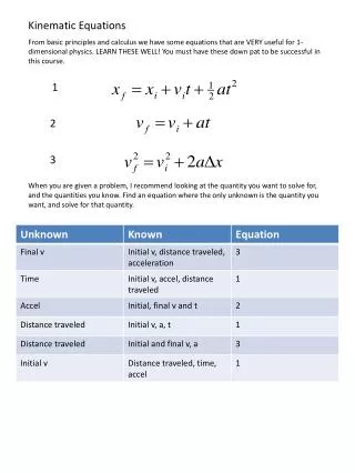
Figure 3. Sandwich plate Table 1. Results for thick square sandwich plate with a / h = 2 Numerical Examples 1. Simply Supported Sandwich Plate under Sinusoidal Loading Analytical solution
Figure 4. Distribution of transverse shear stresses S13 and S23 through the thickness of the sandwich plate for I1 = I2 = I3 =7: present analysis ( ) and Pagano’s solution () Figure 5. Accuracy of satisfying the boundary conditions i(-h / 2) and i(h / 2)on the bottom () and top () surfaces of the sandwich plate: (a) a / h = 2 and (b) a / h = 4 , where i = lgSi3 – Si3 3D
2. Antisymmetric Angle-Ply Plate under Sinusoidal Loading Analytical solution Table 2. Results for square (b = a) two-layer angle-ply plate with h1 = h2 = h / 2 , a / h = 4 and stacking sequence [-15/ 15] ̃ ̃
Table 3. Results for rectangular (b = 3a) two-layer angle-ply plate with h1 = h2 = h / 2 , a / h = 4 and stacking sequence [-15/ 15] ̃ ̃ ̃ Figure 6. Distribution of transverse shear stresses S13 and S23 through the thickness of square unsymmetric two-layer angle-ply plate for I1 = I2 = 7
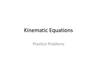
Figure 7. Simply supported cylindrical composite shell with L / R = 4 Table 4. Results for thick two-ply cylindrical shell with R / h = 2 and stacking sequence [0/90] 3. Cylindrical Composite Shell under Sinusoidal Loading Analytical solution
Figure 8. Distribution of transverse shear stresses S13 and S23through the thickness of two-ply cylindrical shell with stacking sequence [0/ 90] for I1 = I2 = 9: present analysis ( ) and Varadan-Bhaskar ‘s 3D solution () Figure 9. Distribution of transverse shear stresses S13 and S23through the thickness of three-ply cylindrical shell with stacking sequence [90/ 0/ 90] for I1 = I2 = I3 = 9: present analysis ( ) and Varadan-Bhaskar ‘s 3D solution ()
Conclusions • A simple and efficient method of SaS inside the shell body has been proposed. This method permits the use of 3D constitutive equations and leads to exact 3D solutions of elasticity for thick and thin laminated plates and shells with a prescribed accuracy • A new higher-order layer-wise theory of shells has been developed through the use of only displacement degrees of freedom, i.e., displacements of SaS. This is straightforward for finite element developments