Download
1 / 28
280 likes | 447 Views
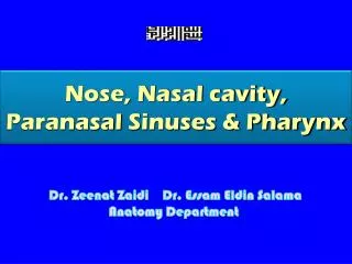
Optimization of an Axial Nose-Tip Cavity for Delaying Ablation Onset in Hypersonic Flow. Sidra I. Silton and David B. Goldstein Center for Aeromechanics Research The University of Texas at Austin January 6, 2003. Motivation. Need for Decreased Heating Hypersonic vehicles

E N D
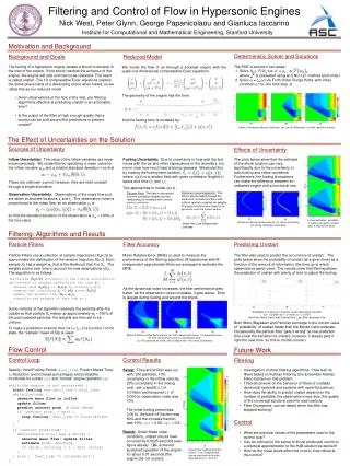
Optimization of an Axial Nose-Tip Cavity for Delaying Ablation Onset in Hypersonic Flow Sidra I. Silton and David B. Goldstein Center for Aeromechanics Research The University of Texas at Austin January 6, 2003
Motivation • Need for Decreased Heating • Hypersonic vehicles • High stagnation point heating • Ablation causes perturbations in flight path • Previous Work • Passive method to reduce heating • Yuceil – experimental • Engblom – numerical • Forward-Facing Cavities • Shock oscillations • Decrease in surface heating • Cooling Mechanism
Objectives • Develop understanding of unsteady flow physics • Effect of different cavity geometries • Surface heating • Ablation onset
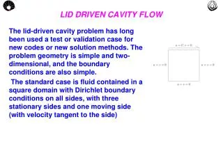
Experimental Methodology • Wind Tunnel Conditions • T¥= 64K • Tstag = 370K • P¥= 4693.8Pa • Model Development • Ice • fiberglass reinforced • frozen in LN2 • Mold and spindle • Shield
After Tunnel Start Wind Tunnel Mounted Model During Tunnel Start
Numerical Methodology • Commercial Codes • INCA • COYOTE • Procedure
Numerical Methodology • Commercial Codes • INCA • COYOTE • Procedure • Assumptions • Flowfield • Emulate experimental conditions • 2D axisymmetric • Laminar • Isothermal wall temperature of 100K • Solid Body • 2D axisymmetric • Initial uniform temperature of 100K or 163K (benchmark study) • Ignored sublimation effects • Variable material properties of ice
Parameter Study • Extensive Experiments • Simulations for geometry showing delayed ablation onset • Nose-Tip Geometry • Dn=2.54 cm • Cavity Dimensions Investigated • Length, L • Lip radius, r • Diameter, D
L/D Parameter Study • Experiments • r = 0.795 mm, D = 1.113 cm • r = 1.191 mm, D = 1.031 cm • L/D varied from 2.0 to 5.0
L/D Parameter Study • Experiments • r = 0.795 mm, D = 1.113 cm • r = 1.191 mm, D = 1.031 cm • L/D varied from 2.0 to 5.0 • Numerical Simulations • r = 1.191 mm, D = 1.031 cm, L/D = 2.0 (geometry 8) • r = 1.191 mm, D = 1.031 cm, L/D = 4.0 (geometry 12)
tonset=1.46 sec tonset=1.79 sec L/D Numerical Results • Mean bow shock speed decreases with increasing L/D • Oscillation frequency decreases with increased cavity depth • drms approximately constant • Mean surface heating increases with L/D • Ablation onset occurs earlier for L/D=4.0 • Shallower cavity may be transitioning in experiments
Lip Radius Parameter Study • Experiments • D = 1.27 cm, L/D=3.5, 4.0, 4.5 • r varied from 1.191 mm to 3.175 mm
Lip Radius Parameter Study • Experiments • D = 1.27 cm, L/D=3.5, 4.0, 4.5 • r varied from 1.191 mm to 3.175 mm • Numerical Simulations • r = 1.191 mm, D = 1.27 cm, L/D = 4.0 (geometry 24) • r = 3.175 mm, D = 1.27 cm, L/D = 4.0 (geometry 29)
Lip Radius Numerical Results • Mean bow shock speed decreased with increasing lip radius • Oscillation frequency approximately constant • dmean increased with lip radius • drms decreased with increased lip radius • Pressure waves coalesce into shock • Inside cavity for r = 1.191 mm • Waves propagate through heat flux • At cavity lip for r = 3.175 mm
Lip Radius Mean Heat Flux Geometry 24 Geometry 29 tonset=1.5 sec tonset=3.6 sec
Diameter Parameter Study • Experiments • D = 0.762 cm, L/D = 4.0 • r = 1.905 mm, 3.175 mm, 4.445 mm • D = 1.27 cm , L/D = 4.0 • r = 1.984 mm, 3.175 mm • D = 1.778 cm, L/D = 4.0 • r = 1.905 mm
Diameter Parameter Study • Experiments • D = 0.762 cm, L/D = 4.0 • r = 1.905 mm, 3.175 mm, 4.445 mm • D = 1.27 cm , L/D = 4.0 • r = 1.984 mm, 3.175 mm • D = 1.778 cm, L/D = 4.0 • r = 1.905 mm • Numerical Simulations • r/(Dn-D) = 0.25, L/D = 4.0 • D = 0.762 cm,1.27 cm, 1.778 cm (geometries 38, 29, 43)
Diameter Numerical Results • Mean bow shock speed decreases with increasing diameter • Oscillation frequency decreased with increasing depth (L/D=constant) • dmean and drms increased with increasing diameter • Large Diameter Cavity • Pressure waves coalesce into shock inside cavity • Waves propagate through heat flux • Small Diameter Cavity • Very little bow shock movement • Cavity remains cold (T=250K)
Diameter Mean Heat Flux Geometry 43 Geometry 38 Geometry 29
Conclusions • Parameter Study • Experimental parameter study • Computational flow visualization • Best experimental configurations • Confirms most experimental findings • Flow may indeed be transitioning for sharper cavities • Optimal nose-tip configuration • Delayed ablation onset • constant nose diameter means increasing drag • constant drag means decreasing nose diameter • Geometry • L/D=4.0, r/(Dn-D)=0.25, D/Dn = 0.5