Download
1 / 26
260 likes | 461 Views
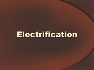
Flow electrification by cavity QED. T. V. Prevenslik 11F, Greenburg Court Discovery Bay, Hong Kong. Contents. Historical background Contact electrification Purpose QED Theory Flow analysis Conclusions. . Historical background.

E N D
Flow electrification by cavity QED T. V. Prevenslik 11F, Greenburg Court Discovery Bay, Hong Kong
Contents Historical background Contact electrification Purpose QED Theory Flow analysis Conclusions
Historical background 1950Streaming current Zeta potential induced by impurity ions 1980 Electrification density ionic charges as double layer at the wall interface 2001 Physiochemical corrosion-oxidation ... No evidence of corrosion products … Streaming currents shear stress Source never identified
Contact electrification Contact and Balancing of Fermi levels thermodynamic equilibrium Only one contact necessary for equilibrium - independent of materials. Experiment shows equilibrium is reached in a single contact only for metals - many contacts are necessary to achieve equilibrium between metals and insulators. Some mechanism - in addition to the balancing of Fermi levels - is at play
Cavity QED induced photoelectric effect Two-step model contact and separation Interface is a high frequency QED cavity that inhibits low frequency IR radiation from thermal kT energy inherent in atomic clusters. IR energy released concentrates to VUV levels in the surfaces of the metal and insulator Electrons are produced by the photoelectric effect.
Purpose Extend the cavity QED induced photoelectric effect in the Two-step model of contact electrification to flow electrification.
Theoretical background Piping system and laminar flow QED cavities in hydraulic oils Comparison of contact and flow electrification Available EM energy Photoelectric effect
Pipe Pump Receiving tank Piping system Hydraulic fluid is pumped in laminar flow through small diameter - long pipe Loop is closed as the fluid falls into an open receiving tank and pumped back to the supply plenum. Air enters the fluid in falling into receiving tank - usually through the pump . Air Air
Velocity Frictional stress Pressure Poiseuille Eqn. Laminar flow relations
Microscope studies show cavities form in laminar flow near surface of boundaries 30 mm Flow 10 mm Depth 1.5 mm Washio et al, Proc Instn Mech Engrs, 215 Part J, (2001) 373 Laminar flow and QED Cavities Light and electron emission occurs over dimensions from walls less than 100 mm Light emission precedes electron emission - similar to photoelectric effect
QED cavities in hydraulic oils Air clusters in flowing hydrocarbon liquids Tearing of oil during flow Tearing and QED electrification Source of EM energy
Air clusters in hydraulic oil Oil Vapor bubbles Px < Pvap Air bubbles Px < Pair Air bubbles likely as Pair >> Pvap Air enters the system through the open tank Solubility of air in hydraulic oils is significant [Ostwald coefficient ~ 10 by volume] Large air bubbles not likely by surface tension Air dissolved throughout oil as nano- clusters of air ( N2 and O2 molecules )
Tearing of oil during flow Maximum tension theory [ Joseph, J Fluid Mech 366 (1998) 367] Cavitation in laminar flow is explained as viscous shear stress produces tensile stress at 45° to wall Tearing of oil occurs if nominal tensile stress is raised above the rupture stress of oil because of the stress concentration of air clusters Tearing separates oil from itself or boundary wall leaving an evacuated space with oil clusters
Flow Tearing and QED electrification Tearing produces vacuum spaces with oil clusters Spaces are a high frequency QED cavities that briefly suppress low frequency IR radiation from oil clusters. Suppressed IR energy loss is conserved by a gain to VUV levels in adjacent oil and wall surfaces Electrons are produced by the photoelectric effect.
Source of EM energy Oil molecule has thermal kT energy Molecules are harmonic oscillators At ambient temperature, thermal kT energy is equivalent to the molecule emitting IR radiation
Oscillator and IR radiation At T ~ 300 K, kT~0.025 eV Saturation at l ~ 100 mm Most of IR energy in oil molecule occurs: l > 20 mm If QED cavity confines IR radiation to l < 20 mm, most of thermal kT energy is suppressed
2R 2R0 IR Oil cluster formation Hydrostatic compression - IR uninhibited Hydrostatic tension - IR inhibited Surface tension S limits the radius R of the oil cluster that can be formed, R> R0 Heptane R0 ~ 0.4 mm
Spherical cluster energy Energy density ~ Degrees of freedom k ~ Boltzmann’s constant IR energy in oil cluster
Air cluster E Flow + VIS Photon R0 R e- D Oil cluster E Wall - Cavity QED momentarily suppresses IR radiation from cluster Conservation of energy requires the prompt release of IR radiation Multi-IR photons combine to VUV levels VUV energy emitted by cluster Electrons and VIS photons produced
Number of VUV photons Number of electrons Electron Yield Ndof = 6 EVUV = 4.9 eV Photoelectric effect
Wall Flow d D Cluster + Fragment e- E - 1-D Resonance l~ 2 D Suppression of IR D < 10 mm Flow electrification Oil clusters and fragments in contact with wall separate at entrance IR radiation is suppressed and released as VUV Electrons are freed from oil Wall is charged negative and oil positive
Summary Flow electrification occurs as oil ruptures in a tearing action Rupture takes place if the tensile stress at a point exceeds the pressure at which the air dissolved in oil, usually atmospheric pressure Air clusters uniformly distributed throughout the volume of the oil act as local stress concentrators for rupture Electron charge Number of oil clusters volume Electrical current is proportional to volume flow rate [ Current = Charge density x volume flow rate] Current not proportional to surface area of the wall
- Poiseiulle Flow Analysis Streaming current I Re x - flow experiment I A( Px-Patm ) - electrical analogy NeQ replaces the flow Q Ne is the electron density Since NeNOC Px-1 NcPx-1
1.4 1.2 1 0.24 mm 0.8 Current density I / Q x 104 C/m3 0.58 mm 0.6 1.25 mm 0.4 0.2 0 0 500 1000 1500 2000 Reynold's number Re Chen et al, Ind Eng Chem Res. 35 (1996) 3195 Volumetric current density
Conclusions Flow and contact electrification obey the same physics - Inhibited IR to VUV by cavity QED QED cavity is an evacuated space containing oil clusters that briefly forms as the oil ruptures and tears under tensile stress Tearing is governed by the tensile stress given by the maximum tension theory Cavity QED converts thermal kT energy to VUV The analytical I and I / Q relations derived are reasonable approximations of flow electrification data for a volume charge relation. An area charge relation does not correlate with the data