Download

1 / 47
470 likes | 594 Views
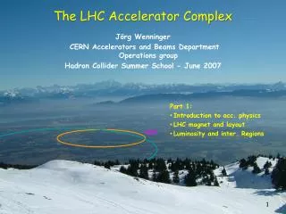
The LHC Accelerator Complex. J örg Wenninger CERN Accelerators and Beams Department Operations group Hadron Collider Summer School - June 2007. Part 2: LHC injector chain Machine Protection Collimation Commissioning and operations. The LHC Injectors. The LHC injector complex.

E N D
The LHC Accelerator Complex JörgWenninger CERN Accelerators and Beams Department Operations group Hadron Collider Summer School - June 2007 • Part 2: • LHC injector chain • Machine Protection • Collimation • Commissioning and operations
The LHC injector complex • The CERN Proton Injectors: • Linac 2 (1979) • Proton Synchrotron Booster (4 superposed rings !) - PSB (1972) • Proton Synchrotron – PS (1959) • Super Proton Synchrotron – SPS (1976) • The PSB-PS-SPS Complex had to be upgraded in order to provide the beams with the appropriate intensity, pattern (25 ns spacing) and size for the LHC ! • Two 3 km long new transfer lines had to be build to transfer the 450 GeV SPS beam to the LHC. • The last item to be commissioned in this chain is the transfer line for the injection into ring 1 (injected in IR2/ALICE). The commissioning will happen in September 2007. • The injectors have a delicate task, because protons ‘remember’ everything you do to them – in particular the harmful things that increase the beam size !
Beam 2 5 LHC 6 4 Beam 1 7 3 TI8 SPS 2 8 TI2 Booster 1 protons LINACS Top energy/GeVCircumference/m Linac 0.12 30 PSB 1.4 157 CPS 26 628 = 4 PSB SPS 450 6’911 = 11 x PS LHC 7000 26’657 = 27/7 x SPS CPS Ions LEIR Note the energy gain/machine of 10 to 20 – and not more ! The gain is typical for the useful range of magnets !!!
Principle of injection (and extraction) Circulating beam Kicker B-field Injected beam Injected beam Septum magnet B B time Kicker magnet Circulating beam Kicker magnet • A septum dipole magnet (with thin coil) is used to bring the injected beam close to the circulating beam. • A fast pulsing dipole magnet (‘kicker’) is fired synchronously with the arrival of the injected beam: deflects the injected beam onto the circulating beam path. • ‘Stack’ the injected beams one behind the other. • At the LHC the septum deflects in the horizontal plane, the kicker in the vertical plane (to fit to the geometry of the tunnels). • Extraction is identical, but the process is reversed !
Principle of injector cycling The beams are handed from one accel. to the next or used for its own customers ! B field SPS top energy, prepare for transfer … SPS ramp Beam transfer SPS waits at injection to be filled by PS SPS B field time PS B time PS Booster time
Bunch patterns The nominal bunch pattern of the LHC is created by combining and splitting of bunches in the injector chain : 6 booster bunches are injected into the PS. Each of the 6 bunches are split into 12 smaller bunches in the PS, yielding a total of 72 bunches at extraction from the PS. Between 2 and 4 batches of 72 bunches are injected into the SPS, yielding between 144 and 288 bunches at extraction from the SPS. A sequence of 12 extraction of 144 to 288 bunches from the SPS are injected into the LHC.
Bunch Splitting at the PS • The bunch splitting in the PS machine is the most delicate operation that is performed in the injector chain. • The quality of the splitting is critical for the LHC (uniform intensity in all bunches…).
Bunch pattern details • The nominal LHC pattern consists of 39 groups of 72 bunches (spaced by 25 ns), with variable spacing between the groups to accommodate the rise times of the fast injection and extraction magnets (‘kickers’). • There is a long 3 ms hole (t5)for the LHC dump kicker (see later). 72 bunches t5 t3 t2 t1
Beam at the gate to the LHC (TI8 line) • The LHC injectors are ready after a long battle to achieve the nominal beam brightness: instabilities, e-clouds etc. • The nominal LHC beam can be produced at 450 GeV in the SPS. TV screen at end transfer line Beam image taken less than 50 m away from the LHC tunnel in IR8 (LHCb) !
The price of high fields & high luminosity… • When the LHC is operated at 7 TeV with its design luminosity & intensity, • the LHC magnets store a huge amount of energy in their magnetic fields: • per dipole magnet Estored = 7 MJ • all magnets Estored = 10.4 GJ • the 2808 LHC bunches store a large amount of kinetic energy: • Ebunch = N x E = 1.15 x 1011 x 7 TeV = 129 kJ • Ebeam = k x Ebunch = 2808 x Ebunch= 362 MJ • To ensure safe operation (i.e. without damage) we must be able to dispose of all that energy safely ! • This is the role of Machine Protection !
Stored Energy • Increase with respect to existing accelerators : • A factor 2 in magnetic field • A factor 7 in beam energy • A factor 200 in stored energy
Comparison… The energy of an A380 at 700 km/hour corresponds to the energy stored in the LHC magnet system : Sufficient to heat up and melt 12 tons of Copper!! • 90 kg of TNT The energy stored in one LHC beam corresponds approximately to… • 8 litres of gasoline • 15 kg of chocolate It’s how ease the energy is released that matters most !!
DFB Cryostat HTS Current Leads Power Converter Powering superconducting magnets • The magnet is cooled down to 1.9K or 4.5K • Installed in a cryostat. • The magnet must be powered • Room temperatur power converters supply the current. • The magnet must be connected • By superconducting cables inside the cryostat. • By normal conducting cables outside the cryostat. • The superconducting cables must be connected to normal conducting cables • Connection via current leads inside special cryostat (DFB)
LHC powering in sectors • To limit the stored energy within one electrical circuit, the LHC is powered by sectors. • The main dipole circuits are split into 8 sectors to bring down the stored energy to ~1 GJ/sector. • Each main sector (~2.9 km) includes 154 dipole magnets (powered by a single power converter) and ~50 quadrupoles. • This also facilitates the commissioning that can be done sector by sector ! 5 4 6 DC Power feed LHC 7 3 DC Power 27 km Circumference Powering Sector 8 2 1 Sector
Powering from room temperature source… 6 kA power converter Water cooled 13 kA Copper cables ! Not superconducting !
…to the cryostat Feedboxes (‘DFB’) : transition from Copper cable to super-conductor Cooled Cu cables
Quench • A quench is the phase transition from the super-conducting to a normal conducting state. • Quenches are initiated by an energy in the order of few mJ • Movement of the superconductor by several m (friction and heat dissipation). • Beam losses. • Cooling failures. • ... • When part of a magnet quenches, the conductor becomes resistive, which can lead to excessive local energy deposition (temperature rise !!) due to the appearance of Ohmic losses. To protect the magnet: • The quench must be detected: a voltage appears over the coil (R ~ 0 to R > 0). • The energy release is distributed over the entire magnet by force-quenching the coils using quench heaters (such that the entire magnet quenches !). • The magnet current has to be switched off within << 1 second.
Quench - discharge of the energy Power Converter Discharge resistor Magnet 1 Magnet 2 Magnet 154 Magnet i • Protection of the magnet after a quench: • The quench is detected by measuring the voltage increase over coil. • The energy is distributed in the magnet by force-quenching using quench heaters. • The current in the quenched magnet decays in < 200 ms. • The current of all other magnets flows through the bypass diode (triggered by the voltage increase over the magnet) that can stand the current for 100-200 s. • The current of all other magnets is dischared into the dump resistors.
Dump resistors Those large air-cooled resistors can absorb the 1 GJ stored in the dipole magnets (they heat up to few hundred degrees Celsius).
If it does not work… During magnet testing the 7 MJ stored in one magnet were released into one spot of the coil (inter-turn short) P.Pugnat
Beam induced damage test The effect of a high intensity beam impacting on equipment is not so easy to evaluate, in particular when you are looking for damage : heating, melting, vaporization … • Controlled experiment: • Special target (sandwich of Tin, Steel, Copper plates) installed in an SPS transfer line. • Impact of 450 GeV LHC beam (beam size σx/y ~ 1 mm) Beam 25 cm
Damage potential of high energy beams • Controlled experiment with 450 GeV beam to benchmark simulations: • Melting point of Copper is reached for an impact of 2.5×10¹² p, damage at 5×10¹² p. • Stainless steel is not damaged with 7×10¹² p. • Results agree with simulation. • Effect of beam impact depends strongly on impact angles, beam size… A B D C Based on those results LHC has a limit for safe beam at 450 GeV of 1012 protons ~ 0.3% of the total intensity Scaling the results yields a limit @ 7 TeVof 1010 protons ~ 0.003% of the total intensity Safe beam = No damage !
vaporisation melting Full LHC beam deflected into copper target Copper target 2808 bunches 2 m Energy density [GeV/cm3] on target axis Target length [cm] The beam will drill a hole along the target axis !!
Schematic layout of beam dump system in IR6 When it is time to get rid of the beams (also in case of emergency!) , the beams are ‘kicked’ out of the ring by a system of kicker magnets and send into a dump block ! Septum magnets deflect the extracted beam vertically Beam 1 Kicker magnets to paint (dilute) the beam Q5L Beam dump block Q4L about 700 m 15 fast ‘kicker’ magnets deflect the beam to the outside Q4R about 500 m Q5R quadrupoles Beam 2
The dump block • This is the ONLY element in the LHC that can withstand the impact of the full beam ! • The block is made of graphite (low Z material) to spread out the hadronic showers over a large volume. • It is actually necessary to paint the beam over the surface to keep the peak energy densities at a tolerable level ! beam absorber (graphite) Approx. 8 m concrete shielding
…takes shape ! CERN visit McEwen 28
‘Unscheduled’ beam loss due to failures In the event a failureor unacceptable beam lifetime, the beammust bedumpedimmediately and safely into thebeam dump block Two main classes for failures (with more subtle sub-classes): • Passive protection • - Failure prevention (high reliability systems). • Intercept beam with collimators and absorber blocks. • Active protection systems have no time to react ! Beam loss over a single turn during injection, beam dump or any other fast ‘kick’. Active Protection - Failure detection (by beam and/or equipment monitoring) with fast reaction time (< 1 ms). - Fire beam dumping system Beam loss over multiple turns due to many types of failures.
LHC Devices LHC Devices LHC Devices Movable Devices BCM Beam Loss Experimental Magnets Collimator Positions Environmental parameters BTV screens Mirrors Safe Mach. Param. Software Interlocks SEQ CCC Operator Buttons Experiments Transverse Feedback Beam Aperture Kickers Collimation System FBCM Lifetime BTV PIC essential + auxiliary circuits WIC FMCM BLM Access System Vacuum System RF System BPM in IR6 Monitors in arcs (several 1000) Monitors aperture limits (some 100) Magnets Power Converters Doors EIS Vacuum valves Access Safety Blocks RF Stoppers QPS (several 1000) Power Converters ~1500 AUG UPS Cryo OK Interlock system Over 10’000 signals enter the interlock system of the LHC !! Timing Beam Dumping System Beam Interlock System Safe Beam Flag Injection BIS Timing System (Post Mortem)
Example : beam loss monitors • Ionization chambers to detect beam losses: • N2 gas filling at 100 mbar over-pressure, voltage 1.5 kV • Sensitive volume 1.5 l • Reaction time ~ ½ turn (40 ms) • Very large dynamic range (> 106) • There are ~3600 chambers distributed over the ring to detect abnormal beam losses and if necessary trigger a beam abort !
Operational margin of SC magnet The LHC is ~1000 times more critical than TEVATRON, HERA, RHIC Applied Field [T] Bccritical field Bc quench with fast loss of ~106-7 protons 8.3 T / 7 TeV QUENCH Tccritical temperature quench with fast loss of ~1010 protons Tc 0.54 T / 450 GeV 1.9 K 9 K Temperature [K]
Beam lifetime • Consider a beam with a lifetime t : • Number of protons lost per second for different lifetimes (nominal intensity): • t = 100 hours ~ 109 p/s • t = 25 hours ~ 4x10⁹ p/s • t = 1 hour ~ 1011 p/s • While ‘normal’ lifetimes will be in the range of 10-100 hours (in collisions most of the protons are actually lost in the experiments !!), one has to anticipate short periods of low lifetimes. • To survive periods of low lifetime (down to 0.2 hours) we must intercept the protons that are lost with very very high efficiency before they can quench a superconducting magnet : collimation! Quench level ~ 106-7 p
Beam collimation • A multi-stage halo cleaning (collimation) system has been designed to protect the sensitive LHC magnets from beam induced quenches : • Halo particles are first scattered by the primary collimator (closest to the beam). • The scattered particles (forming the secondary halo) are absorbed by the secondary collimators, or scattered to form the tertiary halo. • More than 100 collimators jaws are needed for the nominal LHC beam. • Primary and secondary collimators are made of Carbon to survive severe beam impacts ! • The collimators must be very precisely aligned (< 0.1 mm) to guarantee a high efficiency above 99.9% at nominal intensities. • the collimators will have a strong influence on detector backgrounds !! Experiment Protection devices Primary collimator Secondary collimators Tertiary collimators Triplet magnets Absorbers Tertiary halo hadronic showers Primary halo particle Secondary halo + hadronic showers Beam It’s not easy to stop 7 TeV protons !!
Collimator settings at 7 TeV • For colliders like HERA, TEVATRON, RHIC, LEP collimators are/were used to reduce backgrounds in the experiments ! But the machines can/could actually operate without collimators ! • At the LHC collimators are essential for machine operation as soon as we have more than a few % of the nominal beam intensity ! The collimator opening corresponds roughly to the size of Spain ! 1 mm Opening ~3-5 mm
RF contacts for guiding image currents Beam spot
LHC Commissioning • Commissioning of the LHC equipment (‘Hardware commissioning’) has started in 2005 and is now in full progress. This phase includes: • Testing of ~10000 magnets (most of them superconducting). • 27 km of cryogenic distribution line (QRL). • 4 vacuum systems, each 27 km long. • > 1600 magnet circuits with their power converters (60 A to 13000 kA). • Protection systems for magnets and power converters. • Checkout of beam monitoring devices • Etc…
Commissioning status • Magnet production is completed. • Installation and interconnections in progress, few magnets still to be put in place. • Cryogenic system : one sector (IR8IR7) is cooled down to 1.9 K. • Powering system: commissioning started • - Power converters commissioning ~ 80% done. • - Commissioning of the first complete circuits (converter and magnet) has started in IR8. The first quadrupoles have been tested to full current. • Tests of the main dipole circuits in the cold sector are expected • to start THIS week. • Other systems (RF, beam injection and extraction, beam instrumentation, collimation, interlocks, etc) are essentially on schedule for first beam in 2007/8.
First quenches …. Current decay in ~ 0.2 seconds Quench !
Towards beam • Commissioning is progressing smoothly, maybe a bit more slowly than ‘planned’. • Problems discovered so far: • In the sector 7-8 that is cooled down to 1.9 K, a re-analysis of test data has revealed the presence of a dipole with a potentially damaged coil (inter-turn short). This sector must be warmed up in the summer and the magnet replaced. • The triplet magnets provided by FNAL suffer from a design problem of the support structure that must be repaired (in situ for all magnets except the one that was damaged). • A new schedule has been released end of May: • Beam commissioning should start in the spring/early summer of 2008. • A test of one sector with beam has been scheduled for December 2007. This will take beam from IR8 through LHCb to IR7 where the beam is dumped on a collimator.
Beam commissioning • Beam commissioning will proceed in phases with increased complexity: • Number of bunches and bunch intensity. • Crossing angle (start without crossing angle !). • Less focusing at the collision point (larger ‘b*’). • It cannot be excluded that initially the LHC will operate at 6 TeV or so due to magnet ‘stability’. Experience will tell… It will most likely take YEARS to reach design luminosity !!!
The LHC machine cycle collisions beam dump energy ramp collisions 7 TeV start of the ramp Squeeze injection phase preparation and access 450 GeV
LHC operation : injection The ‘normal’ injection sequence into a ring is expected to be: Inject a single bunch into the empty machine: Check parameters etc… and ensure that it circulates with reasonable lifetime. Inject an intermediate beam of ~ 12 bunches: Once the low intensity circulates, inject this higher intensity to fine tune parameters, adjust/check collimators and protection devices etc. Once the machine is in good shape, switch to nominal injections: Each ring requires 12 injections from the SPS, with a repetition rate of 1 every ~25 seconds. This last phase will last ~ 10 minutes. Once it is ‘tuned’ the injection phase should take ~ 20 minutes. …
Ramp and squeeze • One both beam are injected, they will be ramped to 7 TeV in 20 minutes. • At 7 TeV : • the beams are ‘squeezed’: the optics in IR1 and IR5 is changed to bring down the b* (beam size at the collision point) from 10-18 m to the nominal b* of 0.5 m (or whatever value is desired). The machine becomes much more sensitive to perturbations as b* is reduced, that is why it is done at 7 TeV. • the beams are brought into collision: the magnets that kept the beams separated at the collision points are switched off. First collisions… • collimator settings are re-tuned, beam parameters are adjusted to optimize lifetime, reduce backgrounds etc (if needed). • all this is probably going to take ~ ½ hour… • Finally collisions for N hours : probably between 10 and 24 hours. • - The duration results from an optimization of the overall machine efficiency… • - The faster the turn-around time, the shorter the runs (higher luminosity !).
..and we count on YOU to make sense of what comes out the beams !!!!