Download
1 / 41
430 likes | 586 Views
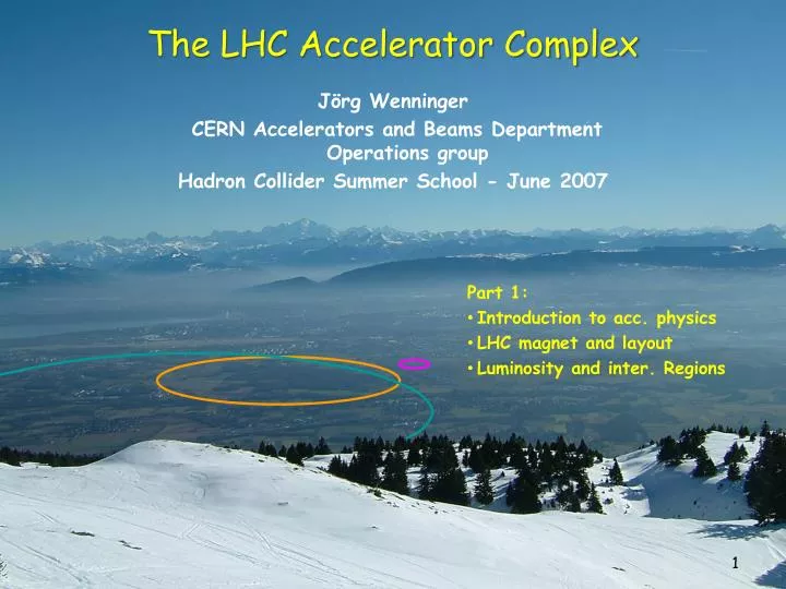
The LHC Accelerator Complex. J örg Wenninger CERN Accelerators and Beams Department Operations group Hadron Collider Summer School - June 2007. Part 1: Introduction to acc. physics LHC magnet and layout Luminosity and inter. Regions. Outline. The LHC challenges

E N D
The LHC Accelerator Complex JörgWenninger CERN Accelerators and Beams Department Operations group Hadron Collider Summer School - June 2007 • Part 1: • Introduction to acc. physics • LHC magnet and layout • Luminosity and inter. Regions
Outline • The LHC challenges • Introduction to magnets and particle focusing • LHC magnets and arc layout • LHC luminosity and interaction regions • LHC injector chain • Machine protection • Collimation • LHC commissioning and operation Part 1 Part 2
LHC History 1982 : First studies for the LHC project 1983 : Z0/W discovered at SPS proton antiproton collider (SppbarS) 1989 : Start of LEP operation (Z boson-factory) 1994 : Approval of the LHC by the CERN Council 1996 : Final decision to start the LHC construction 1996 : LEP operation > 80 GeV (W boson -factory) 2000 : Last year of LEP operation above 100 GeV 2002 : LEP equipment removed 2003 : Start of the LHC installation 2005 : Start of LHC hardware commissioning 2008 : Expected LHC commissioning with beam
CMS ATLAS • 7 years of construction to replace : • LEP: 1989-2000 • e+e- collider • 4 experiments • max. energy 104 GeV • circumference 26.7 km • in the same tunnel by • LHC : 2008-2020+ • proton-proton & ion-ion collider in the LEP tunnel • 4+ experiments • energy 7 TeV LHCB ALICE
Tunnel circumference 26.7 km, tunnel diameter 3.8 m Depth : ~ 70-140 m – tunnel is inclined by ~ 1.4%
LHC – yet another collider? • The LHC surpasses existing accelerators/colliders in 2 aspects : • The energy of the beam of 7 TeV that is achieved within the size constraints of the existing 26.7 km LEP tunnel. • LHC dipole field 8.3 T • HERA/Tevatron ~ 4 T • The luminosity of the collider that will reach unprecedented values for a hadron machine: • LHC pp ~ 1034 cm-2 s-1 • Tevatron pp 2x1032 cm-2 s-1 • SppbarS pp 6x1030 cm-2 s-1 • The combination of very high field magnets and very high beam intensities required to reach the luminosity targets makes operation of the LHC a great challenge ! A factor 2 in field A factor 4 in size A factor 100 in luminosity
y s B v F x Field challenges The force on a charged particle is given by the Lorentz force which is proportional to the charge, and to the vector product of velocity and magnetic field: • To reach a momentum of 7 TeV/c given the LHC (LEP) bending radius of 2805 m: • Bending field B = 8.33 Tesla • Superconducting magnets • To collide two counter-rotating proton beams, the beams must be in separate vaccum chambers (in the bending sections) with opposite B field direction. • There are actually 2 LHCs and the magnets have a 2-magnets-in-one design!
Luminosity challenges The event rate N for a physics process with cross-section s is proprotional to the collider Luminosity L: k = number of bunches = 2808 N = no. protons per bunch = 1.15×10¹¹ f = revolution frequency = 11.25 kHz s*x,s*y = beam sizes at collision point (hor./vert.) = 16 mm • To maximize L: • Many bunches (k) • Many protons per bunch (N) • A small beam size s*u = (b *e)1/2 • b*: characterizes the beam envelope (optics), varies along the ring, mim. at the collision points. • e: is the phase space volume occupied by the beam (constant along the ring). High beam “brillance” N/e (particles per phase space volume) Injector chain performance ! Small envelope Strong focusing !
y s B v F x Dipole fields • Dipole magnets are the simplest accelerator magnets and have ‘just’ 2 poles. • Their field is constant across the magnet. • They are used to bend the beam and define the reference path. • The dipoles define the beam MOMENTUM ! B South y x North
Quadrupolar field - focusing • A quadrupole magnet has 4 poles, 2 north and 2 south. • The poles are arranged symmetrically around the axis of the magnet. • There is no magnetic field along the central axis. • The field increases linearly with distance to the axis. y B x • In a given plane, the quadrupole has the same properties like a classical optical lens. f
Focusing But a quadrupole differsfrom an opticallens : It isfocusing in one plane, defocusing in the other !!! y y Looking in the direction of the particles x x x y Focusing in the vertical plane Defocusing in the horizontal plane s s
Accelerator lattice horizontal plane Focusing in both planes isachieved by a succession of focusing and defocusing quadrupole magnets : The FODO structure vertical plane
LHC arc lattice • Dipole- und Quadrupol magnets • Provide a stable trajectory for particles with nominal momentum. • Sextupole magnets • Correct the trajectories for off momentum particles (‚chromatic‘ errors). • Multipole-corrector magnets • Sextupole - and decapole corrector magnets at end of dipoles • Used to compensate field imperfections if the dipole magnets. To stabilize trajectories for particles at larger amplitudes – beam lifetime !
Beam envelope CMS collision point ARC cells ARC cells Fits through the hole of a needle! • The envelope of the size beam is given by the so-called ‘b’-function ( optics): • In the arcs the optics follows a regular pattern. • In the long straight sections, the optics is matched to the ‘telescope’ that provides very strong focusing at the collision point. • Collision point size (rms, defined by ‘b*’): • CMS & ATLAS : 16 mm LHCb : 22 – 160 mm ALICE :16 mm (ions) / >160 mm (p)
Acceleration • Acceleration is performed using electric fields that are fed into Radio-Frequency (RF) cavities. RF cavities are basically resonators tuned to a selected frequency. • To accelerate a proton to 7 TeV, a potential of 7 TV must be provided to the beam: • In circular accelerators the acceleration is done in small steps, turn after turn. • At the LHC the acceleration from 450 GeV to 7 TeV lasts ~ 20 minutes, with an average energy gain of ~ 0.5 MeV on each turn. s
LHC RF system • The LHC RF system operates at 400 MHz. • It is composed of 16 superconducting cavities, 8 per beam. • Peak accelerating voltage of 16 MV/beam. • For LEP at 104 GeV : 3600 MV/beam ! The LHC beam radiates a sufficient amount of visible photons to be actually observable with a camera ! (total power ~ 0.2 W/m)
RF buckets and bunches The particles oscillate back and forth in time/energy The particles are trapped in the RF voltage: this gives the bunch structure RF Voltage 2.5 ns time E LHC bunch spacing = 25 ns = 10 buckets 7.5 m RF bucket time 2.5 ns 450 GeV 7 TeV RMS bunch length 11.2 cm 7.6 cm RMS energy spread 0.031% 0.011%
Superconductivity • The very high DIPOLE field of 8.3 Tesla required to achieve 7 TeV/c can only be obtained with superconducting magnets ! • The material determines: Tccritical temperature Bc critical field • The cable production determines: • Jc critical current density • Lower temperature increased current density higher fields. • Typical for NbTi @ 4.2 K 2000 A/mm2 @ 6T • To reach 8-10 T, the temperature must be lowered to 1.9 K – superfluid Helium ! Bc Tc
The superconducting cable 6 m 1 mm A.Verweij Typical value for operation at 8T and 1.9 K: 800 A width 15 mm Rutherford cable A.Verweij
Coils for dipoles Dipole length 15 m The coils must be aligned very precisely to ensure a good field quality (i.e. ‘pure’ dipole)
Iron Non-magnetic collars Beam Superconducting coil Dipole field map - cross-section B = 8.33 Tesla I = 11800 A L = 0.1 H
Ferromagnetic iron Non-magnetic collars Superconducting coil Beam tube Steel cylinder for Helium Insulation vacuum Vacuum tank Supports Weight (magnet + cryostat) ~ 30 tons, Length 15 m Rüdiger Schmidt 24
Regular arc: Magnets 1232 main dipoles + 3700 multipole corrector magnets (sextupole, octupole, decapole) 392 main quadrupoles + 2500 corrector magnets (dipole, sextupole, octupole) J. Wenninger - ETHZ - December 2005 25
Connection via service module and jumper Static bath of superfluid helium at 1.9 K in cooling loops of 110 m length Supply and recovery of helium with 26 km long cryogenic distribution line Regular arc: Cryogenics J. Wenninger - ETHZ - December 2005 26
Beam vacuum for Beam 1 + Beam 2 Insulation vacuum for the magnet cryostats Insulation vacuum for the cryogenic distribution line Regular arc: Vacuum J. Wenninger - ETHZ - December 2005 27
Along the arc about several thousand electronic crates (radiation tolerant) for: quench protection, power converters for orbit correctors and instrumentation (beam, vacuum + cryogenics) Regular arc: Electronics J. Wenninger - ETHZ - December 2005 28
Complex interconnects Many complex connections of super-conducting cable that will be buried in a cryostat once the work is finished. This SC cable carries 12’000 A for the main dipoles CERN visit McEwen
Vacuum chamber • The beams circulate in two ultra-high vacuum chambers made of Copper that are cooled to T = 4-20 K. • A beam screen protects the bore of the magnet from image currents, synchrotron light etc from the beam. 50 mm 36 mm Beam screen Beamenvel. ~ 1.8 mm @ 7 TeV Cooling channel (Helium) Magnet bore
LHC Layout • 8 arcs. • 8 long straight sections (insertions), ~ 700 m long. • beam 1 : clockwise • beam 2 : counter-clockwise • The beams exchange their positions (inside/outside) in 4 points to ensure that both rings have the same circumference ! Beam dump blocks IR5:CMS IR6: Beam dumping system IR4: RF + Beam instrumentation IR3: Momentum collimation (normal conductingmagnets) IR7: Betatron collimation (normal conductingmagnets) The main dipole magnets define the geometry of the circle ! IR8: LHC-B IR2:ALICE IR1: ATLAS Injection ring 2 Injection ring 1
Luminosity • Let us look at the different factors in this formula, and what we can do to maximize L, and what limitations we may encounter !! • f : the revolution frequency is given by the circumference, f=11.246 kHz. • N : the bunch population – N=1.15x10¹¹ protons • - Injectors (brighter beams) • - Collective interactions of the particles • - Beam encounters • k : the number of bunches – k=2808 • - Injectors (more beam) • - Collective interactions of the particles • - Interaction regions • - Beam encounters • s* : the size at the collision point –s*y=s*x=16 mm • - Injectors (brighter beams) • - More focusing – stronger quadrupoles For k = 1:
Collective (in-)stability • The electromagnetic field of a bunch interacts with the chamber walls (finite resistivity !), cavities, discontinuities etc that it encounters: • The fields act back on the bunch itself or on following bunches. • Since the fields induced by of a bunch increase with bunch intensity, the bunches may become COLLECTIVELY unstable beyond a certain intensity, leading to poor lifetime or massive looses intensity loss. • Such effects can be very strong in the LHC injectors, and they will also affect the LHC – in particular because we have a lot of carbon collimators (see later) that have a very bad influence on beam stability ! • limits the intensity per bunch and per beam !
Electron clouds… • … affect high intensity beams with positive charge and closely spaced bunches. • Electrons are generated at the vacuum chamber surface by beam impact, photons… • If the probability to emit secondary e- is high (enough), more e- are produced and accelerated by the field of a following bunch(es) and multiplication start… • The cloud of e- that may build up can drive the beam unstable, and at the LHC, overload the cryogenic system by the heat they deposit on the chamber walls ! • This effect depends strongly on surface conditions, simulations are tricky because they are very sensitive to very low energy (~ eV) electrons. The latest simulation indicate that the problem may be less severe than initially anticipated but … • The cloud can ‘cure itself’ because the impact of all those electrons cleans the surface, reduces the electron emission probability and eventually the cloud disappears ! Bunch N+2 accelerates the e-, more multiplication… Bunch N+1 accelerates the e-, multiplication at impact Bunch N liberates an e- e- e- N+2 N+1 N ++++++ ++++++ ++++++ e-
‘Beam-beam’ interaction • When a particle of one beam encounters the opposing beam at the collision point, it senses the fields of the opposing beam. • Due to the typically Gaussian shape of the beams in the transverse direction, the field (force) on this particle is non-linear, in particular at large amplitudes ! • The effect of the non-linear fields can become so strong (when the beams are intense) that large amplitude particles become unstable and are lost from the machine: • poor lifetime • background • THE INTERACTION OF THE BEAMS SETS A LIMIT ON THE BUNCH INTENSITY! Quadrupole lens Beam(-beam) lens
Combining the beams for collisions • The 2 LHC beams circulate in separate vacuum chambers in most of the ring, but they must be brought together to collide. • Over a distance of about 260 m, the beams circulate in the same vacuum chamber and they are a total of ~ 120 encounters in ATLAS, CMS, ALICE and LHCb.
IP Crossing angles • Since every collision adds to our ‘Beam-beam budget’ we must avoid un-necessary direct beam encounters where the beams share a common vacuum: • COLLIDE WITH A CROSSING ANGLE IN ONE PLANE ! • There is a price to pay : • A reduction of the luminosity due to the finite bunch length of 7.6 cm and the non-head on collisions L reduction of ~ 17%. • Crossing planes & angles • ALTAS Vertical 280 mrad • CMS Horizontal 280 mrad • LHCb Horizontal 300 mrad • ALICE Vertical 400 mrad 7.5 m
Interaction region layout 46 m • The quadrupoles are focusing for beam 1, defocusing for beam 2, and vice-versa ! • The final focus is made with the high gradient and large aperture ‘triplet’ quadrupoles (US-JAPAN) : • - Large beam size ~ 100 x size at IP • - Large beam separation from crossing angle ~ 12 mm • Beam sizes : • at IP (ATLAS, CMS) 16 mm • in the triplets ~1.6 mm • in the arcs ~0.2 mm
Tevatron • The TEVATRON is presently the ‘energy frontier’ collider in operation at FNAL, with a beam energy of 980 GeV and a size of ~ ¼ LHC. • It is the first super-conducting collider ever build. • It collides proton and anti-protonbunches that circulate in opposite directions in the SAME vacuum chamber. • The TEVATRON has undergone a number of remarkable upgrades and it presently collides 36 proton with 36 anti-proton bunches (k=36), with bunch populations (N) similar to the ones of the LHC (but there are always fewer anti-protons !). • One of the problems at the TEVATRON are the long-distance encounters of the bunches in the arc sections. A complicated separation scheme with electrostatic elements has to be used: Luminosity gain of LHC comes basically from k !! Tricky to operate !! E E