Download
1 / 21
210 likes | 213 Views
Comp 410 AOS. Packet Switching. These slides derived from Computer Networking: A Top Down Approach , 5 th edition. Jim Kurose, Keith Ross Addison-Wesley, April 2009. mesh of interconnected routers the fundamental question: how is data transferred through net?

E N D
Comp 410 AOS Packet Switching These slides derived from Computer Networking: A Top Down Approach ,5th edition. Jim Kurose, Keith RossAddison-Wesley, April 2009. Introduction
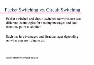
mesh of interconnected routers the fundamental question: how is data transferred through net? circuit switching: dedicated circuit per call: telephone net packet-switching: data sent thru net in discrete “chunks” The Network Core Resources reserved Resources allocated on demand. Core Resources: buffers, link transmission rate Introduction
The internet is packet switched Telephone network is circuit switched The Network Core Introduction
End-end resources reserved for “call” link bandwidth, switch capacity dedicated resources: no sharing circuit-like (guaranteed) performance call setup required State maintained Data transferred at a guaranteed rate Network Core: Circuit Switching Introduction
End-end resources reserved for “call” Links between circuit switches Each link can support n circuits There can be n simultaneous connections. Each circuit thus gets 1/n of the link’s bandwidth. Network Core: Circuit Switching Introduction
network resources (e.g., bandwidth) divided into “pieces” pieces allocated to calls resource piece idle if not used by owning call (no sharing) When two hosts want to communicate network establishes a dedicated end-to-end connection between the hosts. Network Core: Circuit Switching • dividing link bandwidth into “pieces” • frequency division • time division Introduction
Circuit switching: analysis • Disadvantages: • Network resources are wasted during “silent” times (when no one is talking but still connected) • Establishing end-to-end circuits and reserving end-to-end bandwidth is complicated and requires complex signaling software. • Advantage: • Guaranteed bandwith and transmission time • Necessary for some applications (streamed music/video) Introduction
Network Core: Packet Switching transmission: • Each end-end data stream divided into packets • Each packet travels through communication links • Links connected by packet switches • Routers • Or link-level switches. • Switches use store-and-forward transmission • Switch receives entire packet before it transmits any of it again Introduction
Network Core: Packet Switching transmission: Introduction
each end-end data stream divided into packets user A, B packets share network resources each packet uses full link bandwidth resources used as needed Bandwidth division into “pieces” Dedicated allocation Resource reservation Network Core: Packet Switching Introduction
This Figure: takes L/R seconds to transmit (push out) packet of L bits on to link at R bps store and forward: entire packet must arrive at router before it can be transmitted on next link delay = 3L/R (assuming zero propagation delay) Example: L = 7.5 Mbits R = 1.5 Mbps transmission delay = ?? 15 sec Packet-switching: store-and-forward L R R R more on delay shortly … Introduction
Network Core: Packet Switching Switching delays: • Each switch has multiple links • Each link has buffer • If packet arrives and another packet is already being transmitted on that link, must wait in queue • Called queuing delay. • Varies depending on network congestion • Packet loss: queue is full when packet arrives. Introduction
Sequence of A & B packets does not have fixed pattern, bandwidth shared on demand statistical multiplexing. TDM: each host gets same slot in revolving TDM frame. D E Packet Switching: Statistical Multiplexing 100 Mb/s Ethernet C A statistical multiplexing 1.5 Mb/s B On-demand sharing of resources is called statistical multiplexing queue of packets waiting for output link Introduction
1 Mb/s link For each user assume: 100 kb/s when “active” active 10% of time circuit-switching: 10 users packet switching: with 35 users, probability > 10 active at same time is less than .0004 Packet switching allows more users to use network! Packet switching versus circuit switching N users 1 Mbps link Q: how did we get value 0.0004? Introduction
Routing • How do packets make their way through packet-switched Networks? Introduction
roughly hierarchical at center: “tier-1” ISPs (e.g., Verizon, Sprint, AT&T, Cable and Wireless), national/international coverage treat each other as equals Tier-1 providers interconnect (peer) privately Internet structure: network of networks Tier 1 ISP Tier 1 ISP Tier 1 ISP Introduction
“tier-1” ISPs Form their own network Each tier-1 ISP is connected directly to each of the other tier-1 ISPs Each tier-1 ISP is connected to many tier-2 ISPs Tier-1 providers know as the internet backbone Internet structure: network of networks Tier 1 ISP No group officially sanctions tier-1 status! Tier 1 ISP Tier 1 ISP Introduction
POP: point-of-presence to/from backbone peering … …. … … … to/from customers Tier-1 ISP: e.g., Sprint Introduction
“Tier-2” ISPs: smaller (often regional) ISPs Connect to one or more tier-1 ISPs, possibly other tier-2 ISPs Tier-2 ISPs also peer privately with each other. • Tier-2 ISP pays tier-1 ISP for connectivity to rest of Internet • tier-2 ISP is customer of tier-1 provider Tier-2 ISP Tier-2 ISP Tier-2 ISP Tier-2 ISP Tier-2 ISP Internet structure: network of networks Tier 1 ISP Tier 1 ISP Tier 1 ISP Introduction
“Tier-3” ISPs and local ISPs last hop (“access”) network (closest to end systems) Tier 3 ISP local ISP local ISP local ISP local ISP local ISP local ISP local ISP local ISP Local and tier- 3 ISPs are customers of higher tier ISPs connecting them to rest of Internet Tier-2 ISP Tier-2 ISP Tier-2 ISP Tier-2 ISP Tier-2 ISP Internet structure: network of networks Points of Presence (POP): a link or the group of routers in an ISP where other ISPs or customers connect. Tier 1 ISP Tier 1 ISP Tier 1 ISP Introduction
a packet passes through many networks! Tier 3 ISP local ISP local ISP local ISP local ISP local ISP local ISP local ISP local ISP Tier-2 ISP Tier-2 ISP Tier-2 ISP Tier-2 ISP Tier-2 ISP Internet structure: network of networks Tier 1 ISP Tier 1 ISP Tier 1 ISP Introduction