Download
1 / 26
260 likes | 443 Views
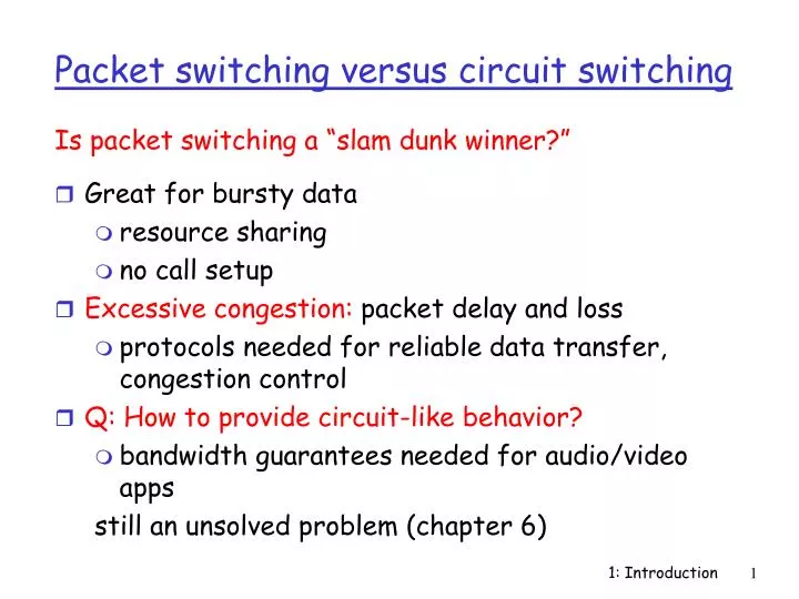
Great for bursty data resource sharing no call setup Excessive congestion: packet delay and loss protocols needed for reliable data transfer, congestion control Q: How to provide circuit-like behavior? bandwidth guarantees needed for audio/video apps still an unsolved problem (chapter 6).

E N D
Great for bursty data resource sharing no call setup Excessive congestion: packet delay and loss protocols needed for reliable data transfer, congestion control Q: How to provide circuit-like behavior? bandwidth guarantees needed for audio/video apps still an unsolved problem (chapter 6) Is packet switching a “slam dunk winner?” Packet switching versus circuit switching 1: Introduction
Goal: move packets among routers from source to destination we’ll study several path selection algorithms (chapter 4) datagram network: destination address determines next hop routes may change during session analogy: driving, asking directions virtual circuit network: each packet carries tag (virtual circuit ID), tag determines next hop fixed path determined at call setup time, remains fixed thru call routers maintain per-call state Packet-switched networks: routing 1: Introduction
Q: How to connect end systems to edge router? residential access nets institutional access networks (school, company) mobile access networks Keep in mind: bandwidth (bits per second) of access network? shared or dedicated? Access networks and physical media 1: Introduction
Dialup via modem up to 56Kbps direct access to router (conceptually) ISDN: integrated services digital network: 128Kbps all-digital connection to router ADSL: asymmetric digital subscriber line up to 1 Mbps home-to-router up to 8 Mbps router-to-home ADSL deployment - 2 million lines in U.S. and Canada Residential access: point to point access 1: Introduction
HFC: hybrid fiber coax asymmetric: up to 10Mbps downstream, 1 Mbps upstream network of cable and fiber attaches homes to ISP router shared access to router among homes issues: congestion, dimensioning deployment: available via cable companies, e.g., MediaOne Residential access: cable modems 1: Introduction
company/univ local area network (LAN) connects end system to edge router Ethernet: shared or dedicated cable connects end system and router 10 Mbs, 100Mbps, Gigabit Ethernet deployment: institutions, home LANs soon LANs: chapter 5 Institutional access: local area networks 1: Introduction
shared wireless access network connects end system to router wireless LANs: radio spectrum replaces wire e.g., Lucent Wavelan 10 Mbps wider-area wireless access CDPD: wireless access to ISP router via cellular network router base station mobile hosts Wireless access networks 1: Introduction
physical link: transmitted data bit propagates across link guided media: signals propagate in solid media: copper, fiber unguided media: signals propagate freely e.g., radio Twisted Pair (TP) two insulated copper wires Category 3: traditional phone wires, 10 Mbps ethernet Category 5 TP: 100Mbps ethernet Physical Media 1: Introduction
Coaxial cable: wire (signal carrier) within a wire (shield) baseband: single channel on cable broadband: multiple channel on cable bidirectional common use in 10Mbs Ethernet Physical Media: coax, fiber Fiber optic cable: • glass fiber carrying light pulses • high-speed operation: • 100Mbps Ethernet • high-speed point-to-point transmission (e.g., 5 Gps) • low error rate 1: Introduction
signal carried in electromagnetic spectrum no physical “wire” bidirectional propagation environment effects: reflection obstruction by objects interference Physical media: radio Radio link types: • microwave • e.g. up to 45 Mbps channels • LAN (e.g., waveLAN) • 2Mbps, 11Mbps • wide-area (e.g., cellular) • e.g. CDPD, 10’s Kbps • satellite • up to 50Mbps channel (or multiple smaller channels) • 270 Msec end-end delay • geosynchronous versus LEOS 1: Introduction
packets experience delay on end-to-end path four sources of delay at each hop nodal processing: check bit errors determine output link queuing time waiting at output link for transmission depends on congestion level of router transmission A propagation B nodal processing queuing Delay in packet-switched networks 1: Introduction
Transmission delay: R=link bandwidth (bps) L=packet length (bits) time to send bits into link = L/R Propagation delay: d = length of physical link s = propagation speed in medium (~2x10⁸ m/sec) propagation delay = d/s transmission A propagation B nodal processing queuing Delay in packet-switched networks Note: s and R are very different quantities! 1: Introduction
R=link bandwidth (bps) L=packet length (bits) a=average packet arrival rate Queuing delay (revisited) traffic intensity = La/R • La/R ~ 0: average queueing delay small • La/R -> 1: delays become large • La/R > 1: more “work” arriving than can be serviced, average delay infinite! 1: Introduction
Networks are complex! many “pieces”: hosts routers links of various media applications protocols hardware, software Question: Is there any hope of organizing structure of network? Or at least our discussion of networks? Protocol “Layers” 1: Introduction
ticket (complain) baggage (claim) gates (unload) runway landing airplane routing ticket (purchase) baggage (check) gates (load) runway takeoff airplane routing airplane routing Organization of air travel • a series of steps 1: Introduction
ticket (complain) baggage (claim) gates (unload) runway landing airplane routing ticket (purchase) baggage (check) gates (load) runway takeoff airplane routing airplane routing Organization of air travel: a different view Layers: each layer implements a service • via its own internal-layer actions • relying on services provided by layer below 1: Introduction
Layered air travel: services Counter-to-counter delivery of person+bags baggage-claim-to-baggage-claim delivery people transfer: loading gate to arrival gate runway-to-runway delivery of plane airplane routing from source to destination 1: Introduction
airplane routing airplane routing airplane routing Distributed implementation of layer functionality ticket (complain) baggage (claim) gates (unload) runway landing airplane routing ticket (purchase) baggage (check) gates (load) runway takeoff airplane routing arriving airport Departing airport intermediate air traffic sites 1: Introduction
Why layering? Dealing with complex systems: • explicit structure allows identification, relationship of complex system’s pieces • layered reference model for discussion • modularization eases maintenance, updating of system • change of implementation of layer’s service transparent to rest of system • e.g., change in gate procedure doesn’t affect rest of system • layering considered harmful? 1: Introduction
application: supporting network applications ftp, smtp, http transport: host-host data transfer tcp, udp network: routing of datagrams from source to destination ip, routing protocols link: data transfer between neighboring network elements ppp, ethernet, ATM physical: bits “on the wire” application transport network link physical Internet protocol stack 1: Introduction
Each layer: distributed “entities” implement layer functions at each node entities perform actions, exchange messages with peers network link physical application transport network link physical application transport network link physical application transport network link physical application transport network link physical Layering: logical communication 1: Introduction
E.g.: transport take data from app add addressing, reliability check info to form “datagram” send datagram to peer wait for peer to ack receipt analogy: post office network link physical application transport network link physical application transport network link physical application transport network link physical application transport network link physical data data data ack Layering: logical communication transport transport 1: Introduction
network link physical application transport network link physical application transport network link physical application transport network link physical application transport network link physical data data Layering: physical communication 1: Introduction
M M H H H H H H H H H H H H t t t n l n l t n t n t M M M M application transport network link physical application transport network link physical M M Protocol layering and data Each layer takes data from above • adds header information to create new data unit • passes new data unit to layer below source destination message segment datagram frame 1: Introduction
roughly hierarchical national/international backbone providers (NBPs) e.g. BBN/GTE, Sprint, AT&T, IBM, UUNet interconnect (peer) with each other privately, or at public Network Access Point (NAPs) regional ISPs connect into NBPs local ISP, company connect into regional ISPs local ISP local ISP NAP NAP Internet structure: network of networks regional ISP NBP B NBP A regional ISP 1: Introduction
National Backbone Provider e.g. BBN/GTE US backbone network 1: Introduction