Download
1 / 15
160 likes | 176 Views
Packet Switching. Outline Store-and-Forward Switches Bridges and Extended LANs Cell Switching Segmentation and Reassembly. Packet Switching. Problem: “Not all networks are Directly Connected” Directly connected networks have two limitations: - number of hosts that can be accommodated

E N D
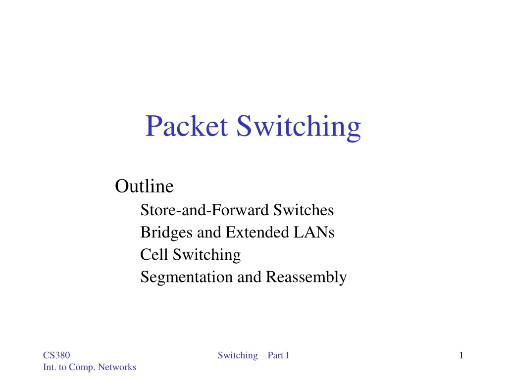
Packet Switching Outline Store-and-Forward Switches Bridges and Extended LANs Cell Switching Segmentation and Reassembly Switching – Part I
Packet Switching • Problem: “Not all networks are Directly Connected” • Directly connected networks have two limitations: - number of hosts that can be accommodated - geographic limitation • Goal – networks that are global in scale • Like Telephone using (circuit) switches, we use packet switches(store-and-forward) that take packets that arrive on an input and forward (switch) them to the right output. Two ways to do it: - connection - connectionless Switching – Part I
Packet Switching • Key problems that a switch must deal with: • Contention – packet arrival exceeds packet dispatch (in this chapter) • Congestion – packets discards (due to running out of buffer space) too frequently (in future chapter) • Key issues covered - forwarding - contention • Two switching technologies - LAN switching – Popular in LAN, evolved from Ethernet bridging - Asynchronous Transfer Mode(ATM) – popular in WAN Switching – Part I
Star Topology • Large numbers of switches can be connected • Connecting switches/hosts using Point-to-Point links • Scaling doesn’t always mean performance (switches designed with enough aggregate capacity) Switching – Part I
T3 T3 Switch T3 T3 STS-1 STS-1 Input Output ports ports Scalable Networks • Switch • forwards packets from input port to output port, this is referred to as either switching or forwarding. In terms of the OSI architecture, it is the main function of the network layer. • port selected based on address in packet header • Advantages • cover large geographic area (tolerate latency) • support large numbers of hosts (scalable bandwidth) Switching – Part I
Switches • Q. How does the switch determine output port? • By looking at an identifier in the packet header • Three approaches: • Virtual Circuit (connection-oriented) • Datagram (connectionless) • Source Routing Switching – Part I
Virtual Circuits 0 Switch 1 3 1 2 Switch 2 2 3 1 5 11 • Explicit connection setup (and tear-down) phase • Subsequence packets follow same circuit • Sometimes called connection-oriented model 0 Host A • Two types: • - PVC Permanent Virtual Circuit • Need network administrator configure the state • - SVC “Signalled” Virtual Circuit • Send a message into the network(signalling) • Analogy: phone call • Each switch maintains a VC table 7 0 Switch 3 1 3 4 Host B 2 Switching – Part I
Virtual Circuits Tables VC Table for Switch 1 Incoming Incoming Outgoing Outgoing InterfaceVCIInterfaceVCI 2 0 1 3 1 2 3 1 . . . 0 Switch 1 3 1 2 2 3 1 5 VC Table for Switch 2 11 0 Switch 2 Incoming Incoming Outgoing Outgoing InterfaceVCIInterfaceVCI 3 11 0 0 1 2 0 2 . . . Host A • VCI Virtual Circuit Identifier (0, 1, 2, …) • combined with incoming/outgoing interface (e.g. 0, 1, 2, 3)can uniquely identify the virtual connection (VC) • assigned whenever a new connection is created • not a globally significant identifier for the VC; rather, only on a given link 7 0 Switch 3 1 3 4 Host B 2 Switching – Part I
Example: Give Virtual Circuit Tables for all switches Host C Host E 0 Switch 1 Host D 2 Host F Switch 3 3 1 1 3 1 Switch 2 Host B 2 0 0 2 Host G 3 Host A Host H VC Table for Switch 1 VC Table for Switch 2 VC Table for Switch 3 Switching – Part I
Virtual Circuit Model • Typically wait full RTT for connection setup before sending first data packet. • While the connection request contains the full address for destination, each data packet contains only a small identifier, making the per-packet header overhead small. • If a switch or a link in a connection fails, the connection is broken and a new one needs to be established. • Connection setup provides an opportunity to reserve resources(QoS reservations). • ATM utilizes virtual circuits Switching – Part I
Datagrams • Idea – provide just enough information for the switch to forward the packet Host D Host E 0 Switch 1 Host F 3 1 Switch 2 2 Host C 2 3 1 • No setup time • Independent forwarding packets • Analogy – postal system • Each switch maintains a forwarding (routing) table. • More routing in the next chapter 0 Host A 0 Switch 3 Forwarding table for Switch 2 Host B Host G 1 3 2 Host H Switching – Part I
Workstation Used As a Switch Main problem: all packets must pass through a single point of contention. (I/O bus, read to/write from the main memory) Chapter 3, Figure 9Switching – Part I
Forwarding Table for Nodes D A B C • Give the datagram forwarding table for each node: E Node A Node B Node C Node D Node E Switching – Part I
Datagram Model • There is no round trip time delay for connection setup; a host can send data as soon as it is ready. • Source host has no way of knowing if the network is capable of delivering a packet or if the destination host is even up. • Since packets are treated independently, it is possible to route around link and node failures. • Since every packet must carry the full address of the destination, the overhead per packet is higher than for the connection-oriented model. Switching – Part I
Source Routing • Does not need to use either VCs or Datagrams although can be used in combination with • IP for instance uses datagrams but has a source routing option • Can be used for VC setup • Source host contains all • information • - rotates data Switching – Part I