Download
1 / 14
150 likes | 440 Views
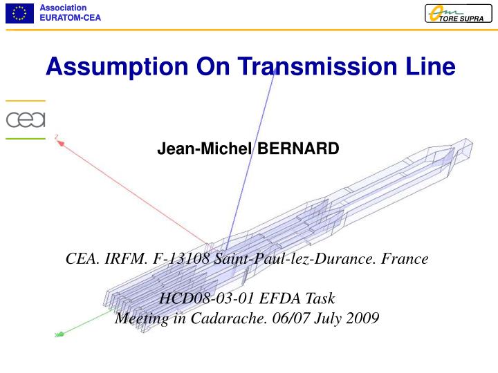
Assumption On Transmission Line. Jean-Michel BERNARD. CEA. IRFM. F-13108 Saint-Paul-lez-Durance. France HCD08-03-01 EFDA Task Meeting in Cadarache. 06/07 July 2009. LH Transmission Line Assumptions. Nb of KLYSTRON = 48 Power available = 500kW/klystron. LH Transmission Line Assumptions.

E N D
Assumption On Transmission Line Jean-Michel BERNARD CEA. IRFM. F-13108 Saint-Paul-lez-Durance. France HCD08-03-01 EFDA Task Meeting in Cadarache. 06/07 July 2009
LH Transmission Line Assumptions Nb of KLYSTRON = 48 Power available = 500kW/klystron
LH Transmission Line Assumptions Equatorial Port Cell Door Wall Thickness = 1.5m Available Larger = 3.95m Available height = 0.61m Available Port Nb = 11 ?? View From IO
LH Transmission Line Assumptions • Assumption 1 : 48 Lines of WC16 Waveguides Power per Waveguide = 500kW Difficulties for Assembly and Dismantling Difficulties to be fixed on the ceiling Difficulties for cooling
LH Transmission Line Assumptions • Assumption 2 : 24 Lines of WC16 Waveguides Power per Waveguide = 1 MW Less Difficulties for Assembly and Dismantling Less Difficulties to be fixed on the ceiling Less Difficulties for cooling Needs 1 MW windows!
LH Transmission Line Assumptions • Power dissipation on Waveguides: • From A.T. WALL Value of Theoretical Attenuation in dB/m in the TE(M) Mode: 7.15x10⁻³ dB/m
LH Transmission Line Assumptions • Power dissipation on Waveguides: • FromFrancescoMIRIZZI(meeting on the 12th May 2009) • From POZAR • From HFSS: 2.25x10⁻³ dB/m 5x10⁻³ dB/m 3x10⁻³ dB/m SUMMARY For 70m length 109 x 24=2.6MW of loss!!!
LH Transmission Line Assumptions • Mechanical Fixed point To protect RF Windows of Klystron from Expansion on waveguides Nearest from the Klystron Possibility to use expansion joint. • Expansion should be for copper waveguide: Dl=16.5 e-6 x 50° (DT) x 70 m (length)=57.75mm • Well Grounding Electrical Spurious on RF Wave Mechanical Needs
LH Transmission Line Assumptions • Waveguide Expansion joint (Bellow)? US Patent R&D Need
LH Transmission Line Assumptions • Number of windows at the rear flange of the Port plug: With 48 windows, Remote handling should be difficult? Rear Flange of the port plug 48 Windows
LH Transmission Line Assumptions Splitter Load From Transmission line and Klystron To Rear Flange of Port Plug From Drawing Nbr: 54/0015/0015/2D/01/00/R DDD2001
LH Transmission Line Assumptions • Electrical Consequence for 24 transmission lines: • Need calibration of phase for each couple of Klystrons. • Only 24 possible tuning point on phase for n// adjustments : • Decrease the n// flexibility.
LH Transmission Line Assumptions CONCLUSION Needs: To define length in building IO must transmit detailed drawing of buildings. To confirm losses in waveguide. To make thermo mechanical analysis on waveguides To design Bellows for expansion joint R&D To design 500 kW or 1 MW windows R&D To design 500 kW or 1 MW DC-breaks R&D Question: • Who?