Download
1 / 32
340 likes | 637 Views
Transmission line. Transmission line. An apparatus to convey energy or signal from one place to another place. Transmitter to an antenna connections between computers in a network hydroelectric generating plant and a substation several miles away

E N D
Transmission line An apparatus to convey energy or signal from one place to another place. • Transmitter to an antenna • connections between computers in a network • hydroelectric generating plant and a substation several miles away • interconnect between components of a stereo system • CATV service provider and your TV set • Connections between devices on a circuit board
Types of transmission lines Microstrip line Coaxial cable Two-wire transmission line
Distribution of electric field strengths of typical TEM lines Microstrip Two-wire Parallel plate E/H distributions vary as the structures of transmission lines change. For electromagnetic compatibility, E/H should be confined to small area.
TEM mode (Transverse electromagnetic mode) Wave Solution
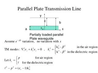
Parallel plate waveguide With a wide enough line trace, variation along y-axis can be ignored.
Transmission line 등가 회로 + + v (z, t) v (z, t) - - i (z, t) i (z+z, t) i (z, t) + L z v (z+ z,t) C z - z z
Transmission line의 특징 H • For a magnetic field and an electric field propagating in the same direction, the ratio of E and H (E+/H+) is kept constant. • For a voltage and a currentcurrent propagating in the same direction, V+/I+ratio is equal to Z0 . • When the ratio is disturbed, reflected waves are generated. Direction of propagation H E
Reflection coefficient + V -
Influence of line length on load voltage + V - + V - + V - + V - + V - Vin Vout R R MLIN R2 VtPulse R1 R=1k Ohm SRC1 R=20 Ohm t Impedance mismatched Z0= 50 Zs = 20 Z0= 50 ZL= 1k 0.5m
Ringing ~ Signal source Load Mismatched load
Impedance matching – Digital logic Source matching ~ Load matching ~
Frequency domain solution β : propagation constant, vp : speed of light
Phasor representation + V -
Transmission line terminated with short, open V inc o Out of phase (180 ) for short Vrefl Zs = Zo o In phase (0 ) for open Vrefl For reflection, a transmission line terminated in a short or open reflects all power back to source
Transmission Line Terminated with 25 Ω V inc Zs = Zo ZL = 25 W Vrefl Standing wave pattern does not go to zero as with short or open
Some transmission line examples case 1) matched load