Download
1 / 35
1.22k likes | 3.1k Views
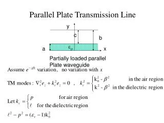
Transmission Line Basics. Alan Murray. Part 1 - Introduction and Basics . Lecture 1. General definition Practical definition Types of transmission line: TE, TM, TEM modes TEM wave equation - equivalent circuit approach Lecture 2. Transmission Line Equations

E N D
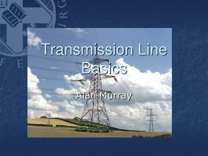
Transmission Line Basics Alan Murray
Part 1 - Introduction and Basics • Lecture 1. General definition • Practical definition • Types of transmission line: TE, TM, TEM modes • TEM wave equation - equivalent circuit approach • Lecture 2. Transmission Line Equations • The "Telegrapher's Equations“ • Solution for lossless transmission lines: F(t±x/v) • Simplest case of F(t±x/v)
Part 1 - Introduction and Basics • Lecture 3. Lines with Losses • Direction of travel of cos/sin (ωt ±βx) waves • Phase velocity of a wave on a transmission line • General transmission line: attenuation
Part 2 - Characteristic Impedance/Reflections • Lecture 4. Current and voltage on a transmission line: • Characteristic impedance, ZO • Characteristic impedance of lossless lines • Characteristic impedance of general lines • Infinitely long transmission lines • Reflections on transmission lines
Part 2 - Characteristic Impedance/Reflections • Lecture 5. Transmission line with change of Z0 • Voltage reflection coefficient • Voltage reflection coefficient at an arbitrary distance l from the load ZL
Part 3 - The Smith Chart and its Applications (Brian Flynn) Lecture 6. Impedances of terminated lines Lecture 7. Introduction to the Smith Chart Lecture 8. Using Smith Chart with load and line combinations Lecture 9. Adding components using a Smith Chart
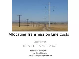
These can all behave liketransmission lines Pair of wires Co-ax cable IC interconnects PCB tracks
General Definition Power transfer(e.g. for lighting, heating, performing work) - examples are mains electricity, microwave guides in a microwave oven, a fibre-optic illuminator. • A transmission line • is a device for propagating or guiding electromagnetic energy from one point to another. This propagation is for one of two general reasons:
General Definition 2. Information transfer – examples are telephone, radio, and fibre-optic links (in each case the energy propagating down the transmission line is modulated in some way).
Example - CE amplifier circuit with a wire behaving as a transmission line. Because signals cannot travel faster than the speed of light, if the voltage at A changes it will take a finite time for the information to reach B – during that time the voltages at A and B will be different.
Example - Voltage and phase difference along a transmission line Generating station Transformer Vm • A remote transformer (B) is connected by a transmission line 600 km long to a generating station (A) supplying 50 Hz AC. • At t = 0 the generator is switched into the line and the generator voltage is at its maximum, Vm. • What are the voltage and phase differences between the ends of the line at the instant power reaches the transformer? 600 km
Example - Voltage and phase difference along a transmission line Generator Transformer VA VB • Signal travels at 3x10⁸ms-1 • Distance = 600kM • T = Distance/Speed • T=0.002s LAG • Period = 0.02s • Lag = 2πx0.002/0.02 • 0.63radians • VB=VAcos(ωt-0.63) • VA=peak .. • VB=0.81Vm
Announcements • Formative feedback • Exam question • Hand in – I will mark in 2 weeks • I will email a question during ILW • EXTRA LECTURE • Friday, 14th February (Valentine’s day!) • Lost a lecture in week#1 (Tuesday) • Wish to hand over if possible before ILW • Apologies for 2xEM/day!
Example - Phase difference between the ends of a cable. λ N.B. one wavelength corresponds to one complete cycle or wave, and hence to a phase change of 360º or 2π radians. So the phase change over a distance L is just 360ºxL / λ (or 2πxL/ λ radians) Determine the phase difference between the ends of: 10m length of mains cable for a 50Hz electricity supply λ=v/f = 3x10⁸/50 = 6x10⁶m Phase change = 2πx10/λ = 2πx10x/6x106=0.0006° (ie ≈0!)
Example - Phase difference between the ends of a cable. λ N.B. one wavelength corresponds to one complete cycle or wave, and hence to a phase change of 360º or 2π radians. So the phase change over a distance L is just 360ºxL / λ (or 2πxL/ λ radians) Determine the phase difference between the ends of: (b) 10m length of coaxial cable, 750MHz TV signal λ=v/f = 3x10⁸/750x106 = 0.4m Phase change = 2πx10/λ =2πx10/0.4=9000° (ie >>0!)
Practical Definition … • We must treat a conducting system as a transmission line if the wavelength, λ, of the signal propagating down the line is less than or comparable with the length, L, of the line: • Associated with transmission lines there may be • Propagation losses • Distortion • Interference due to reflection at the load • Time delays • Phase changes
Different types of transmission lines: Cross section 2-wire line (dc) 2-wire line (ac) Coaxial line (dc, ac, rf) Microstrip line (rf) Rectangular waveguide (rf) Optical fibre (light)
Microstrip line cross section dielectric conductors conductor dielectric
Waveguide rectangular waveguides cross section
Transverse Electric andMagnetic (TEM) Mode E E E H H H ExH
Transverse Electric (TE) Mode E Resultant Eand H fields at 90° to waveguide walls E E H H H
Transverse Magnetic (TM) Mode H H E H E E
Modes of Propagation The energy propagating down a transmission line propagates as an ELECTROMAGNETIC WAVE. Different patterns of E and H fields are possible for these waves. Each pattern constitutes a “mode of propagation”:
Transmission lines - 2 groups Start here! • Grouped according to the type of mode that normally propagates down them. The kinds of mode that can propagate down a line depend on the geometry and materials of the line • LINES PROPAGATING TEM MODES: • No E or H field in the direction of propagation. • twin-wire, coaxial, stripline and (approximately) microstrip lines are in this group. • LINES PROPAGATING TE OR TM MODES: • E or H components in the direction of energy flow. • waveguides and optical fibres are in this group
Equivalent Circuit Approach L R G C • The details of wave propagation can be deduced from Maxwell's Equations. However, TEM guided waves on a transmission line can also be analysed using a lumped equivalent circuit approach • Real transmission lines have: • a resistance per unit length, R • Note that R represents theR/length of both conductors • a capacitance per unit length, C • an inductance per unit length, L • a (leakage) conductance per unit length, G.
For Parallel Wires: ε d a • For wires with d >> a: • a = wire radius • d = wire spacing
For Coaxial Cable: b ε From “Capacitance” lecture a a = radius of inner conductor b = inner radius of outer conductor
LΔx RΔx GΔx CΔx Equivalent Circuit For a Transmission Line Δx • Represent the transmission line by an equivalent circuit • each infinitesimal length of transmission line → 4 (per unit length)components R/G/C/L • To make up the whole line, repeat the equivalent circuit a sufficient number of times.
Primary Line Constants • C = capacitance per unit length Fm-1 • L = inductance per unit length Hm-1 • R = resistance per unit length Ωm-1 • G = conductance per unit length Sm-1 • R, C, L and G are all expressed per unit length • R, G small for a good transmission line. • If R = 0 and G = 0, the line is termed “lossless”.
Worked Example 1.3 RΔx GΔx Z0 Z0→ The rest of the line, which is infinite LΔx CΔx Δx Example 1.3 - Determine an expression for the impedance of an infinite, lossless transmission line.
Worked Example 1.3 X x X x X x x Z0 ΔX→0 Z0→ The rest of the line, which is infinite LΔx CΔx Δx
Worked Example 1.3 Z0→ LΔx Energy CΔx Δx • Is energy “lost”? • No … actually moved to the next section … • Z0 is the characteristic impedance of the line.
Summary • Conductors → transmission line analysis • when the wavelength, λ, of the energy propagating down the line is less than or comparable with the length, L , of the line • Definition of TE, TM & TEM modes − twin-wire, coaxial and strip lines only propagate TEM modes. • Transmission lines have capacitance, inductance and resistances (pre unit length) → equivalent circuit.