Download
1 / 23
340 likes | 1.46k Views
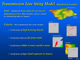
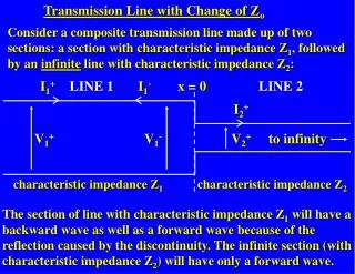
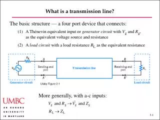
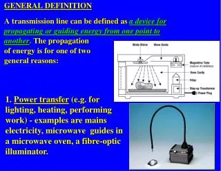
Transmission Line “Definition”. General transmission line: a closed system in which power is transmitted from a source to a destination Our class: only TEM mode transmission lines

E N D
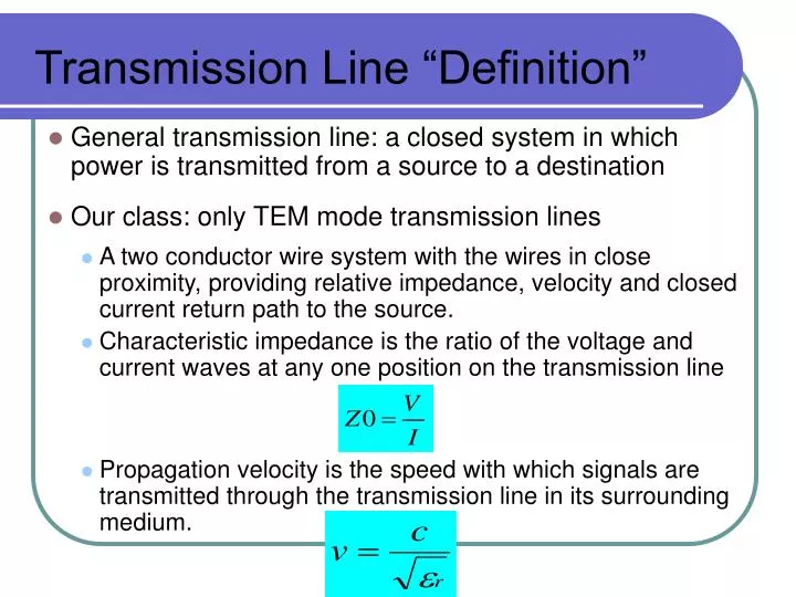
Transmission Line “Definition” • General transmission line: a closed system in which power is transmitted from a source to a destination • Our class: only TEM mode transmission lines • A two conductor wire system with the wires in close proximity, providing relative impedance, velocity and closed current return path to the source. • Characteristic impedance is the ratio of the voltage and current waves at any one position on the transmission line • Propagation velocity is the speed with which signals are transmitted through the transmission line in its surrounding medium.
Presence of Electric and Magnetic Fields • Both Electric and Magnetic fields are present in the transmission lines • These fields are perpendicular to each other and to the direction of wave propagation for TEM mode waves, which is the simplest mode, and assumed for most simulators(except for microstrip lines which assume “quasi-TEM”, which is an approximated equivalent for transient response calculations). • Electric field is established by a potential difference between two conductors. • Implies equivalent circuit model must contain capacitor. • Magnetic field induced by current flowing on the line • Implies equivalent circuit model must contain inductor.
lR0 lL0 lG0 lC0 lR0 lL0 lG0 lC0 T-Line Equivalent Circuit • General Characteristics of Transmission Line • Propagation delay per unit length (T0) { time/distance} [ps/in] • Or Velocity (v0) {distance/ time} [in/ps] • Characteristic Impedance (Z0) • Per-unit-length Capacitance (C0) [pf/in] • Per-unit-length Inductance (L0) [nf/in] • Per-unit-length (Series) Resistance (R0) [W/in] • Per-unit-length (Parallel) Conductance (G0) [S/in]
lL0 lC0 lL0 lC0 Ideal T Line • Ideal (lossless) Characteristics of Transmission Line • Ideal TL assumes: • Uniform line • Perfect (lossless) conductor (R00) • Perfect (lossless) dielectric (G00) • We only consider T0, Z0, C0, and L0. • A transmission line can be represented by a cascaded network (subsections) of these equivalent models. • The smaller the subsection the more accurate the model • The delay for each subsection should be no larger than 1/10th the signal rise time.
Signal Frequency and Edge Rate vs. Lumped or T line Models In theory, all circuits that deliver transient power from one point to another are transmission lines, but if the signal frequency(s) is low compared to the size of the circuit (small), a reasonable approximation can be used to simplify the circuit for calculation of the circuit transient (time vs. voltage or time vs. current) response.
T Line Rules of Thumb So, what are the rules of thumb to use? May treat as lumped Capacitance Use this 10:1 ratio for accurate modeling of transmission lines Td < .1 Tx May treat as RC on-chip, and treat as LC for PC board interconnect Td < .4 Tx
Other “Rules of Thumb” • Frequency knee (Fknee) = 0.35/Tr (so if Tr is 1nS, Fknee is 350MHz) • This is the frequency at which most energy is below • Tr is the 10-90% edge rate of the signal • Assignment: At what frequency can your thumb be used to determine which elements are lumped? • Assume 150 ps/in
When do we need to use transmission line analysis techniques vs. lumped circuit analysis? Tline Wavelength/edge rate When does a T-line become a T-Line? • Whether it is a bump or a mountain depends on the ratio of its size (tline) to the size of the vehicle (signal wavelength) • Similarly, whether or not a line is to be considered as a transmission line depends on the ratio of length of the line (delay) to the wavelength of the applied frequency or the rise/fall edge of the signal
Equations & Formulas How to model & explain transmission line behavior
Relevant Transmission Line Equations Propagation equation is the attenuation (loss) factor is the phase (velocity) factor Characteristic Impedance equation In class problem: Derive the high frequency, lossless approximation for Z0
L 0 = = Z ; T L C ; 0 d 0 0 C 0 T 0 = = C ; L Z T ; 0 0 0 0 Z 0 1 = = me v ; C L ; 0 0 0 me m = m m e = e e ; . r 0 r 0 Ideal Transmission Line Parameters • Knowing any two out of Z0, Td, C0, and L0, the other two can be calculated. • C0 and L0 are reciprocal functions of the line cross-sectional dimensions and are related by constants: • e is electric permittivity • e0= 8.85 X 10⁻¹²F/m (free space) • eri s relative dielectric constant • m is magnetic permeability • m0= 4p X 10-7H/m (free space) • mr is relative permeability Don’t forget these relationships and what they mean!
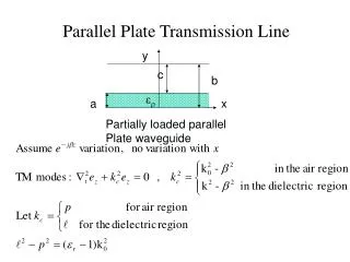
Parallel Plate Approximation • Assumptions • TEM conditions • Uniform dielectric (e ) between conductors • TC<< TD; WC>> TD • T-line characteristics are function of: • Material electric and magnetic properties • Dielectric Thickness (TD) • Width of conductor (WC) • Trade-off • TD; C0 , L0 , Z0 • WC; C0 , L0 , Z0 Base equation To a first order, t-line capacitance and inductance can be approximated using the parallel plate approximation.
Improved Microstrip Formula • Parallel Plate Assumptions + • Large ground plane with zero thickness • To accurately predict microstrip impedance, you must calculate the effective dielectric constant. From Hall, Hall & McCall: Valid when: 0.1 < WC/TD < 2.0 and 1 < er < 15
Improved Stripline Formulas • Same assumptions as used for microstrip apply here From Hall, Hall & McCall: Symmetric (balanced) Stripline Case TD1 = TD2 Valid when WC/(TD1+TD2) < 0.35 and TC/(TD1+TD2) < 0.25 Offset (unbalanced) Stripline Case TD1> TD2
Refection coefficient • Signal on a transmission line can be analyzed by keeping track of and adding reflections and transmissions from the “bumps” (discontinuities) • Refection coefficient • Amount of signal reflected from the “bump” • Frequency domain r=sign(S11)*|S11| • If at load or source the reflection may be called gamma (GL or Gs) • Time domain r is only defined a location • The “bump” • Time domain analysis is causal. • Frequency domain is for all time. • We use similar terms – be careful • Reflection diagrams – more later
Reflection and Transmission Incident 1+r Transmitted r Reflected
A: Terminated in Zo Zs - Zo Zo Zo r = = 0 Zo Vs + Zo Zo B: Short Circuit Zs - 0 Zo r = = - Zo 1 Vs + 0 Zo C: Open Circuit Zs ¥ - Zo Zo r = = 1 Vs ¥ + Zo Special Cases to Remember
Transmission Lines, Reflections, and Termination Short Circuited Line
Transmission Lines, Reflections, and Termination Open Circuited Line
Transmission Lines, Reflections, and Termination If the source impedance (Rsrc) does not equal Z0, then reflections occur at the near end of the line as well as at the far end. Each end of the line has its own value of ρ. The principle of superposition applies, so that voltage at any point on the line and instant in time is the sum of that point’s initial condition and all waves that have passed it so far. The end of a transmission line is said to be matched if it is terminated with its characteristic impedance.
Transmission Lines, Reflections, and Termination Mismatched Line
Transmission Lines, Reflections, and Termination Matched Line
Model • http://www.fourier-series.com/rf-concepts/flash_programs/Reflection/index.html