Download
1 / 14
140 likes | 300 Views
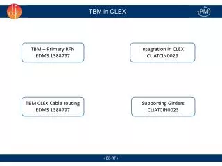
Integration of CLIC TBM in CLEX Electronics allocation and cables tracing. Wilfrid Farabolini (CEA/IRFU) 16 October 2013. Cables and racks request. Collected by Alexander Summarized by Dmitry. Cables separation due to EMC constraints. 14640 mm 2. 6 racks + 1 spare.

E N D
Integration of CLIC TBM in CLEX Electronics allocation and cables tracing Wilfrid Farabolini (CEA/IRFU) 16 October 2013
Cables and racks request Collected by Alexander Summarized by Dmitry Cables separation due to EMC constraints 14640 mm2 6 racks + 1 spare 5 holes + 1 spare
1st idea: additional drills on the ceiling CALIFES TBL CLIC Module Pros: - Minimum changes to the building Cons: - Delicate drilling (present cable tray and TBL line to be removed, dust inside) - Cables length > 20 m if to follow present cable trays - Problem to install new racks in the gallery - Staff in the gallery during operations
Shortest path from Module to Gallery Drill only on same rows as the present pits - building structure to be preserved – drilling the ceiling is problematic (GS/SE)
Problem to install the drilling machine Cable tray to be removed Protection from dust and water to be installed TBL equipments to be removed
Even more problems for cable path Cable trenches are full on this side Nothing authorized below air ducts level (transport vehicles) Any other path is very long (40 m for last installed RF cables)
Lack of space in the above gallery Pits positions 2.5 crates available in the vacuum alley (to be negotiated) 3 crates available in the signals acquisition alley (after some rearrangement)
2ndsolution: drill the wall towards CTF2 CALIFES TBL CLIC Module Pros: Simple drilling (Clear area, enough space for dust confinement) Possibility to install racks where are the disused 30 GHz racks Operations from a safer gallery (but still close to the X-Box1) Cons: Long cable length (>> 20 m, inside CLEX electronics required) Radioprotection of the CTF2 area to be investigated
Cables path towards CTF2 Possible drills More clearance but iron wall to be moved Possibility to add a cable tray under the ceiling but long path to reach the module (13 m to the wall) Only 3 crates available in the gallery above CTF2 if disused 30 GHz electronics is removed
Best choice: dedicated shelter on the car park CALIFES Shelter3 x 5 m TBL CLIC Module Pros: Easiest drilling solution (from outside, minimum dust, clear area inside) Shortest possible cables length (< 20 m) Sufficient place to host the new racks Safe and comfortable operations inside the shelter (outside of the controlled area) Cons: New construction (Algeco 1 kCHF/m2) with all services (air conditioning ?) Radioprotection of the car park to be investigated by RP
From Module to car park wall Alternatively use of the ventilation window chicane instead of drilling new holes (to be investigated) - 0.400 x 0.180 m fully available trench - 3.8 m to the wall (2.8 m thick) - Easy drilling of 6 holes (diam. 160 mm) with slope for RP - Still 2 m of trench to be cut to reach the wall
A shelter on car park side Example of a present shelter (high voltage electronics for TL2 tail clipper) 5 x 3 m available Ventilation window
Possible shelter arrangements Dmitry Gudkov 4 x 3 m shelter
Conclusion • The shelter on car park solution allows: • Minimal cable length and easy cables pulling (also a cost issue for “good” RF cables) • Easy crates installation and safe operations (outside controlled area) • Easy drilling of the holes (less building structure concern, drill from outside) • Alternatively possible use of the ventilation window (under investigation by Y. Body – EN-CV) • Possibility to displace some electronics cabinet inside for Rad-Hard tests • Requires cable trench extension (feasibility checked with (GS/SE) ) • RP to give the green light (G. Dumont contacted) • Decision to be taken by March 2014