Download
1 / 21
210 likes | 385 Views
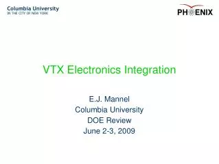
VTX Electronics Integration. E.J. Mannel Columbia University June 9, 2008. Outline. Ground Plan Power Systems Slow Control DCM-2 Status Rack Allocation Design and Safety Reviews Schedule Issues and Concerns. Ground Plan.

E N D
VTX Electronics Integration E.J. Mannel Columbia University June 9, 2008
Eric J. Mannel mannel@nevis.columbia.edu Outline Ground Plan Power Systems Slow Control DCM-2 Status Rack Allocation Design and Safety Reviews Schedule Issues and Concerns
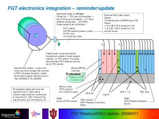
Eric J. Mannel mannel@nevis.columbia.edu Ground Plan Pixel, Strip and FVTX systems electrically isolated from each other Star ground plan Shield around beam pipe Exterior enclosure shield Single Point connections to PHENIX clean ground Floating Power Supplies Optical connections to PHENIX DAQ
Eric J. Mannel mannel@nevis.columbia.edu Pixel Grounding Plan 1.8V Pixel ½ Ladder North LVDO Common Rtn Filter LVDO + Bias 1K-10K Barrel 1 Stave Inter-Barrel Shield North 1.8V Pixel ½ Ladder South LVDO Common Rtn Filter LVDO + Bias 1K-10K Barrel 2 Stave Inter-Barrel Shield South Barrel End Cap Magnet Bridge 3.0V Pixel Bus Supply SPIRO 5.0V Spiro Bias Supply-Floating (50V Max) SPIRO Rack Thermal Plane Safety Ground Support Structure Support Structure PHENIX Clean Ground
Eric J. Mannel mannel@nevis.columbia.edu Bias Power System Bias Power Systems Mini-Pod evaluation system from Wiener/ISEG 0-500 V floating supplies Precision voltage/current monitoring Two crates required for VTX: Crate 1: Pixels, 4 modules- 64 Channels Crate 2: Strips, 3 modules- 48 Channels Performance evaluation on pixel ½ ladder March-May '08 Integration evaluation June-July '08 PHENIX DAQ/ONCS Groups, ISU Summer Students
Eric J. Mannel mannel@nevis.columbia.edu Wiener/ISEG Mini-Pod System • Low frequency noise, random spikes (2mV p-p) • High frequency noise, ~70KHz (10mV p-p) • Tested with prototype 1.5cm pixel ½ ladder • Meets VTX performance requirements
Eric J. Mannel mannel@nevis.columbia.edu Slow Control Systems Regular meetings with PHENIX DAQ/ONCS group on slow control issues. PHENIX DAQ/ONCS group will participate in bias supply integration evaluation, June-July '08 PHENIX DAQ/ONCS group working with C. Pancake on PIXEL FEM slow control integration, June-July '08
Eric J. Mannel mannel@nevis.columbia.edu Detector Collection Module (DCM-2) Status The DCM is the PHENIX standard interface between the detector front end electronics and PHENIX DAQ. Optical interface development complete FE3 Daughter board operational with current DCM Currently being used for HBD Available for system chain tests BNL R&D funding for DCM-2 design and prototype fabrication in place- Q3 FY08. Design work starting with fabrication completion expected by Q4 FY09
Detector Upgrade Rack AllotmentsD. Lynch 2 Racks assigned to VTX Sufficient space for VTX power crates and patch panels. Location ~10 meters from VTX
Eric J. Mannel mannel@nevis.columbia.edu Electronic and Safety Reviews Procedures in place for internal reviews of electronics system designs starting at Pre-production stage. Requires submission of: Schematics Layout Files Relevant Data Sheets/Manuals Q/A Procedures Upon answering all issues from review, design is released for production
Eric J. Mannel mannel@nevis.columbia.edu Electronic and Safety Reviews Currently SPIRO Module has passed production review and preliminary safety review PIXEL Bus has passed preproduction review Working with PHENIX PM and CA-D Experimental Safety Committee to have global safety review for PIXEL system- Fall '08
Eric J. Mannel mannel@nevis.columbia.edu Schedule-Calender Year Electronics Design Reviews as required Pixel System Safety Review: 3Q '08 Bias Supply Procurement: 4Q '08 Pixel Power Supply Design: 3-4Q '08 Pixel Power Supply Procurement: 2Q '09 DCM-2s for Pixel system delivered: 3Q '09 Cable/Fiber Planning/Installation: 1-3Q '09 Rack Installation: 2-3Q '09
Eric J. Mannel mannel@nevis.columbia.edu Issues and Concerns Verifying noise performance of pixel/strip ladders in combined test. Power system design needs to proceed quickly. Rack space and cable plan highly integrated with other PHENIX upgrades. Design schedule for DCM-2 tight for reading out Pixel system in Run-10.
Eric J. Mannel mannel@nevis.columbia.edu Conclusions Ground plan developed and being fine tuned. Design of power systems has started. Evaluation of Bias Supply system in progress Procedure for design and safety reviews. Production SPIRO board review completed Preproduction pixel bus completed Plans for comprehensive pixel safety review in progress
Eric J. Mannel mannel@nevis.columbia.edu Conclusions-2 Slow control integration plan is being developed. Close collaboration with DAQ/ONCS group Evaluation Bias supply system this summer Work on DCM-2s is about to begin Working with PHENIX integration on rack allocation.
Eric J. Mannel mannel@nevis.columbia.edu Backup Slides
Eric J. Mannel mannel@nevis.columbia.edu Pixel Ground Plan Ground one end of the stave to one ½ ladder. Barrel 1 to north ½ ladder. Barrel 2 to south ½ ladder. Provide for a shield between barrels 2 and 3. Option for aluminized mylar between barrels 2 and 3. Floating Power supplies Shared returns between ½ Ladders for LV Optical connections to Pixel FEM
Eric J. Mannel mannel@nevis.columbia.edu Stripixel Ground Plan Each ladder isolated from support Separate analog, digital and bias returns floating at s upply. Quadrants within barrel have common point at power board Power boards tied to PHENIX clean ground Optical Connection to FEM
Eric J. Mannel mannel@nevis.columbia.edu Ladder Bias ROC Analog Digital Power Distribution Card Filter Bias Supply LVDO LVDO ROC Bias Analog Digital Fuse Block PHENIXHigh Power LV System Ladder ROC Bias Analog Digital Filter Bias Supply LVDO LVDO ROC Bias Analog Digital
Eric J. Mannel mannel@nevis.columbia.edu DCM II Function Collect FEM data Zero suppressed data Data Error/ Event Alignment checking Alignment checking via L1 data or/and adjacent data link Pocketsized data Possibility for data processing First stage of event building we need to handle possible link errors associate with increasing radiation. It may not be practical any more to stop run when one link drop out during the run.
Eric J. Mannel mannel@nevis.columbia.edu DCM II Block Diagram ALTERA STRATIX I EP1S30 8 optical links per DCM 5 event buffer Event buffer 320 Mbytes/sec Optics+ De-serializer Zero sup- pression ALTERA STRATIX II EP2S60 L1 data MUX 5 event buffer Event buffer Optics+ De-serializer Zero sup- pression receiver buffer Data link in Alignment FEM DCM link 80 MHz 16 bits/word 1.6Gbits/sec 8b/10b encoding method choose Ti’s TLK2501 as de-serializer STRATIX has 2 Mbits for event data buffer 1 Mbits for processing buffer 30K logical element old DCM has 1K Logical element per optical link Data processing Event Buffer 640 Mbytes/sec MUX Data link out receiver buffer 5 event buffer Event buffer Optics+ De-serializer Zero sup- pression MUX STRATIX II has 1 Mbits for event data buffer 1.5 Mbits for processing buffer 20K - 60 K logical element faster than STRATIX I 5 event buffer Event buffer Optics+ De-serializer Zero sup- pression Alignment ALTERA STRATIX I EP1S30