Download
1 / 11
110 likes | 306 Views
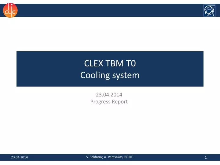
CLEX TBM T0 Cooling system. 23.04.2014 Progress Report. V. Soldatov, A. Vamvakas, BE-RF. 23.04.2014. Schematic layout for the CLEX two-beam module cooling. CLEX TBM phase 3.2. CDR cooling layout (Fig. 5.144 ). The two phases have different cooling requirements.

E N D
CLEX TBM T0Cooling system 23.04.2014 Progress Report V. Soldatov, A. Vamvakas, BE-RF 23.04.2014
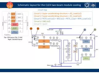
Schematic layout for the CLEX two-beam module cooling CLEX TBM phase 3.2 CDR cooling layout (Fig. 5.144) The two phases have different cooling requirements. • Phase 3.1: One PETS, one SAS, idle PETS loads • Phase 3.2: Two PETS, two SAS The extra cooling circuits for phase 3.2 can be implemented directly or at a later stage 2
Main components • Super accelerating structure • PETS (Ciemat) • RF Loads • Drive Beam Quadrupole by Michele Modena 3
Cooling Scheme At the 02/04/14 CLIC Module Working Group meeting it was decided to use the existing CTF3 cooling network. A mounting rack with all the necessary components will be installed in close proximity to the TBM and the water will be supplied by the CTF3 network.
Using CTF3 Cooling System CLEX TBM MB Girder Main beam Girder COLD WATER 30˚C TERMOSTAT CLEX TBM DB Girder Drive beam Girder Top view CTF3 Water Supply Return (x10) CLEX TBM T0 Module Supporting System Distribution manifold is connected with the equipment by flexible standard Kevlar pipes (approved on 02/04/14 ) Supply (x10) Front view
Cooling rack Return • Independent distribution manifold • Contains all control components • Compact • In close proximity to the TBM • Flexible pipes to central CTF3 cooling system To CTF3 Safety valve 600mm Supply From CTF3 Spares Control valve Flow meter • Most components already tested in • other facilities (CTF3, Xbox) • Control valves yet to be defined • (contacting suppliers under way) 800mm *Preliminary rack design 230mm
Cooling Network of the Module • Example shows the cooling network for the CLEX T0 module with 2 SAS and 2 PETS The cooling network will consist of copper pipes (OD 8, 10 and 16mm) and standard connectors (Swagelok) Assembly Flowchart (link) Circuit 1/2 Circuit 3 7
Circuits specifications Phase 3.1 Phase 3.2 Circuit 1:Super-accelerating structure + (2x) AS_Load Circuit 2:PETS unit + WG + PETS_Load + RFN_Load + (2x)Idle_PETS_Load Circuit 3:(2x) DBQ Circuit 2:PETS unit + WG + PETS_Load + (2x)RFN_Load + (2x)Idle_PETS_Load Circuit 4:Super-accelerating structure #2 + (2x) AS_Load Total flow: 0.38 m3/h *Sizing according to CLEX nominal values 8
DAQ & Control • Control rack in shelter • Standalone system • Option for remote control from CTF3 control room • PID control of component temperature • Similar to LAB modules • Temperature sensors: • components (x16 surface contact sensors) • Water (x11 pipe sensors) • Ambient temperature (x1) • Flow meters (x4) • Pressure sensor (x1) • Control Valves (x4) • Data acquisition system in LAB CTF3 Control Room TBM sensors DAQ & Control Water Flow Cooling rack Control Valves 9
Preliminary Inventory Cooling rack components: DAQ components: • Miscellaneous: • Hand valves, elbows, fittings • Pipes • Cables • Electronics rack • PC 10
Planning and Activities • Completion of the specification • List of equipment • Control requirements Procurement of market components • Detailed design • Cooling Rack • Module Cooling Network • Routing • Control components • Electronics and Software • Control terminal • Monitoring and control software Installation works in CTF2 and CTF3 Approval • Next steps: • procurement of market components • detailed design & integration