Download
1 / 13
160 likes | 870 Views
The individual F/Fs in an n-bit register : numbered in sequence from 0(rightmost position) through n-1The numbering of bits in a 16-bit register : marked on top of the boxA 16-bit register partitioned into two parts : bit 0-7(symbol ?L" Low byte), bit 8-15(symbol ?H" High byte)Register Transfer :

E N D
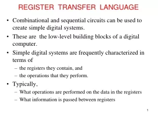
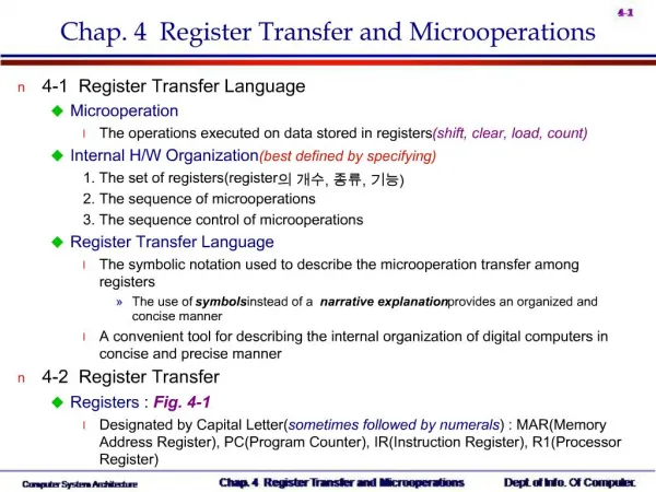
1. Chap. 4 Register Transfer and Microoperations 4-1 Register Transfer Language
Microoperation
The operations executed on data stored in registers(shift, clear, load, count)
Internal H/W Organization(best defined by specifying)
1. The set of registers(register? ??, ??, ??)
2. The sequence of microoperations
3. The sequence control of microoperations
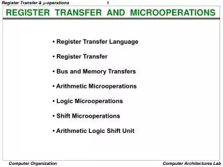
Register Transfer Language
The symbolic notation used to describe the microoperation transfer among registers
The use of symbols instead of a narrative explanation provides an organized and concise manner
A convenient tool for describing the internal organization of digital computers in concise and precise manner
4-2 Register Transfer
Registers : Fig. 4-1
Designated by Capital Letter(sometimes followed by numerals) : MAR(Memory Address Register), PC(Program Counter), IR(Instruction Register), R1(Processor Register)
2. The individual F/Fs in an n-bit register : numbered in sequence from 0(rightmost position) through n-1
The numbering of bits in a 16-bit register : marked on top of the box
A 16-bit register partitioned into two parts : bit 0-7(symbol �L� Low byte), bit 8-15(symbol �H� High byte)
Register Transfer : Information transfer from one register to another
(transfer of the content of register R1 into register R2)
The content of the source register R1 does not change after the transfer
Control Function : The transfer occurs only under a predetermined control condition
The transfer operation is executed by the hardware only if P=1 : Fig. 4-2
A comma is used to separate two or more operations(Executed at the same time)
Basic Symbols for Register Transfer : Tab. 4-1
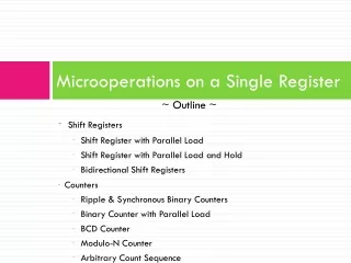
3. 4-3 Bus and Memory Transfers
Common Bus
A more efficient scheme for transferring information between registers in a multiple-register configuration
A bus structure = a set of common lines
Control signals determine which register is selected
One way of constructing a common bus system is with multiplexers
The multiplexers select the source register whose binary information is place on the bus
The construction of a bus system for four registers : Fig. 4-3
4 bit register X 4
Four 4 X 1 Multiplexers
Bus Selection : S0, S1
8 Registers with 16 bit
16 X 1 mux 8 ? ??
4. Bus Transfer
The content of register C is placed on the bus, and the content of the bus is loaded into register R1 by activating its load control input
Three-State Bus Buffers
A bus system can be constructed with three-state gates instead of multiplexers
Tri-State : 0, 1, High-impedance(Open circuit)
Buffer
A device designed to be inserted between other devices to match impedance, to prevent mixed interactions, and to supply additional drive or relay capability
Buffer types are classified as inverting or noninverting
Tri-state buffer gate : Fig. 4-4
When control input =1 : The output is enabled(output Y = input A)
When control input =0 : The output is disabled(output Y = high-impedance)
5. The construction of a bus system with tri-state buffer : Fig. 4-5
The outputs of four buffer are connected together to form a single bus line(Tri-state buffer?? ??? ??)
No more than one buffer may be in the active state at any given time(2 X 4 Decoder???? ??)
To construct a common bus for 4 register with 4 bit : Fig. 4.5? ?? ?? 4 ? ??(register ??? ???? decoder? ?? ?? ? buffer ?? ??)
Memory Transfer
Memory read : A transfer information into DR from the memory word M selected by the address in AR
Memory Write : A transfer information from R1 into the memory word M selected by the address in AR
6. The 4 types of microoperation in digital computers
Register transfer microoperation : Sec 2-4 ? Sec 4-2?? ?? ??
Arithmetic microoperation
Logic microoperation
Shift microoperation
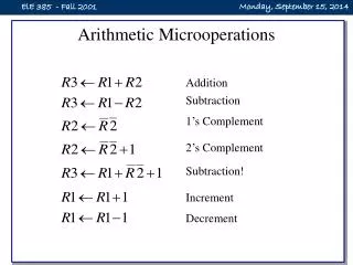
4-4 Arithmetic Microoperation
Arithmetic Microoperation : Tab. 4-3
Negate : 2�s complement
Subtraction : R1 + 2�s complement of R2
Multiplication(shift left), Division(shift right)
4-bit Binary Adder : Fig. 4-6
Full adder = 2-bits sum + previous carry
c0(input carry), c4(output carry)
7. 4-bit Binary Adder-Subtractor : Fig. 4-7
M =0 : Adder B ? M + C = B ? 0 + 0 = B, ? A + B
M =1 : Subtractor B ? M + C = B ? 1 + 1 = B� + 1= -B(2�s comp), ?A - B
4-bit Binary Incrementer
Sequential circuit implementation by using binary counter : Fig. 2-10
Combinational circuit implementation by using Half Adder : Fig. 4-8
8. Arithmetic Circuit
One composite arithmetic circuit in Tab. 4-3 : Fig. 4-9
D= A0(X0) + B0(Y0) + Cin
B0 : S0, S1? ?? B, B, 0, 1
Tab. 4-4? Input Y = B
9. 4-5 Logic Microoperation
Logic microoperation
Logic microoperations consider each bit of the register separately and treat them as binary variables
exam)
Special Symbols
Special symbols will be adopted for the logic microoperations OR(?/), AND(?), and complement(a bar on top), to distinguish them from the corresponding symbols used to express Boolean functions
exam)
List of Logic Microoperation
Truth Table for 16 functions for 2 variables : Tab. 4-5
16 Logic Microoperation : Tab. 4-6
Hardware Implementation
16 microoperation Use only 4(AND, OR, XOR, Complement)
One stage of logic circuit : Fig. 4-10
10. Some Applications
Logic microoperations are very useful for manipulating individual bits or a portion of a word stored in a register
Used to change bit values, delete a group of bits, or insert new bit values
Selective-set
The selective-set operation sets to 1 the bits in register A where there are corresponding 1�s in register B. It does not effect bit positions that have 0�s in B
Selective-complement
The selective-complement operation complements bits in A where there are corresponding 1�s in B. It does not effect bit positions that have 0�s in B
Selective-clear
The selective-clear operation clears to 0 the bits in A only where there are corresponding 1�s in B
Selective-mask
The mask operation is similar to the selective-clear operation except that the bits of A are cleared only where there are corresponding 0�s in B
11. Insert
The insert operation inserts a new value into a group of bits
This is done by first masking the bits and then ORing them with the required value
Clear
The clear operation compares the words in A and B and produces an all 0�s result if the two numbers are equal
4-6 Shift Microoperations
Shift Microoperations : Tab. 4-7
Shift microoperations are used for serial transfer of data
Three types of shift microoperation : Logical, Circular, and Arithmetic
Logical Shift
A logical shift transfers 0 through the serial input
The bit transferred to the end position through the serial input is assumed to be 0 during a logical shift(Zero inserted)
12. Circular Shift(Rotate)
The circular shift circulates the bits of the register around the two ends without loss of information
Arithmetic Shift
An arithmetic shift shifts a signed binary number to the left or right
An arithmetic shift-left multiplies a signed binary number by 2
An arithmetic shift-right divides the number by 2
Arithmetic shifts must leave the sign bit unchanged because the sign of the number remains the same
Shift right :
Sign reversal occur : Overflow F/F Vs=1
13. Hardware Implementation(Shifter) : Fig. 4-12
4-7 Arithmetic Logic Shift Unit
One stage of arithmetic logic shift unit : Fig. 4-13