Download
1 / 29
290 likes | 406 Views
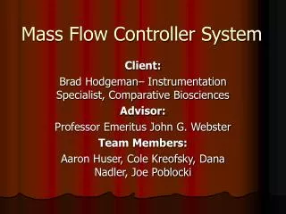
PanSTARRS Gigapixel Array Controller System. Overview Present Status CPU board FPGA board DAQ board Staffing Infrastructure Schedule. Outline. Illustration of Bar Mounting Scheme - 3. OTA flexcables attach to internal

E N D
PanSTARRS Gigapixel Array Controller System • Overview • Present Status • CPU board • FPGA board • DAQ board • Staffing • Infrastructure • Schedule Outline
Illustration of Bar Mounting Scheme - 3 OTA flexcables attach to internal motherboard with amplifiers. A single controller module is shown for reference (1 controller for 4 OTAs). Note: hermetic feedthrough deleted for clarity.
Gigapixel Camera Controller Electronics • Controllers are mounted behind cryostat. • 16 controllers per Gigapixel camera.
Baseline Controller Design OTA OTA OTA OTA OTA OTA OTA OTA OTA OTA OTA OTA OTA OTA OTA OTA OTA OTA OTA OTA OTA OTA OTA OTA OTA OTA OTA OTA OTA OTA OTA OTA OTA OTA OTA OTA OTA OTA OTA OTA OTA OTA OTA OTA OTA OTA OTA OTA OTA OTA OTA OTA OTA OTA OTA OTA OTA OTA OTA OTA OTA OTA OTA OTA IOTA3U IOTA3U IOTA3U IOTA3U IOTA3U IOTA3U IOTA3U IOTA3U IOTA3U IOTA3U IOTA3U IOTA3U IOTA3U IOTA3U IOTA3U IOTA3U LAN Switch 1Gb ethernet Fiber isolated Pixel Server Pixel Server Pixel Server Pixel Server Pixel Server Pixel Server Pixel Server Pixel Server Pixel Server Pixel Server Pixel Server Pixel Server Pixel Server Pixel Server Pixel Server Pixel Server Power Supply 2-row OTA Controller “Rack” • IOTA3U controller operates 4 OTAs • For a 8 x 8 OTA focal plane, 2 rows of 1 x 8 OTA’s • Each row has 8 IOTA3U controllers. 1Gb ethernet
Data Storage Advances • Fiber Broadcast • Second Tier Processing • Back-end LAN+SAN SAN SWITCH • Storage Area Networks and Network Attached Storage • Cost effective high performance • Connectivity to “second tier” processors if needed • Pixel Servers also have built in RAIDs • Lowest cost but performance not benchmarked
1 x 4 IOTA3U Assembly OTA OTA OTA OTA OTA Flexprint PCB • Green areas are custom designed • Blue areas are COTS • 3U hardware could include connectors, front panels, guide rails, cooling components, chassis parts, etc. Flexprint PCB Interface Board Cryostat wall HDC HDC Interface bd Chassis CPCI backplane CPCI backplane Signal chains and ADCs Signal chains and ADCs FPGA COTS CPU FPGA Signal chains and ADCs Signal chains and ADCs COTS CPU board Cooling Cooling COTS 1G ethernet Module wall Front Panel
Mechanical Check 1 x 4 Green crosshatch shows 1 x 4 OTA shadow 4 sets of 2mm metric connectors shown 2 are CompactPCI bus standard 2 for OTA signal processing Standard 3U front panel shown in maroon.
IOTA3U Boards Interface bd CPCI backplane FPGA3U DAQ3U Signal chains and ADCs DAQ3U Signal chains and ADCs COTS CPU board COTS 1G ethernet • COTS CPU board • Baseline LINUX based PowerPC • 1 or 2 channel 1G Ethernet fiber PMC daughterboard • CPCI bus interface • FPGA3U board • CPCI interface • FPGA +1Ge?? • Buffer memory • Data interface to DAQ3U • DAQ3U board • Data interface • FPGA • Buffer memory • Signal Chain and ADCs • Backplanes • CPCI backplane • Interface backplane • Signal fanout • Filtering • Connectors
COTS CPU – Status • Colleagues at CFHT have evaluated an SBS RL4 • PowerPC 7400/750 CPU at 400 to 500MHz • Fast 10/100Mbit Ethernet • PMC extension slot • Conduction cooled option • LINUX support not good • IfA has purchased and received a Menmicro F1N • PowerPC MPC8245/300MHz • 1 Gbit Ethernet daughterboard • LINUX ElinOS support (RTAI also) • STATUS – Under Test
FPGA3U Board Design Support CPLD FPGA PROM Xilinx Virtex 2Pro FPGA 405 PPC Optocoupled Trigger I/O Test Conn Trigger signals Fiber coupled 100BT* /100BT /10 BT JTAG • Virtex2pro FPGA possible centroid/shift calculator Power section Local Xtal 1Gb/100BT PHY 128Mx32 SDRAM Compact PCI Bus 32Kx32 Dual Port RAM Buffer LDVS To DAQ3U
Xilinx ML300 Development Board System ACE FPGA PROM Xilinx Virtex 2Pro 1G PHY FPGA 405 PPC JTAG Fiber coupled 1G ethernet Power section Local Xtal 128MB DDR SDRAM PMC PCI Bus 1394 PHY LDVS RS232 PCMCIA LCD Touch screen Display To DAQ3U Parallel port Keyboard port
DAQ3U Board Design 32 bit pixel read bus Power section Support CPLD FPGA PROM LDVS TBD RAM Xilinx Virtex 2Pro 100BT PHY FPGA 405 PPC Optocoupled Trigger I/O Test Conn Analog Devices 9826 Analog Devices 9826 Analog Devices 9826 Analog Devices 9826 Analog Devices 9826 Analog Devices 9826 3 CCD outputs 3 CCD outputs 3 CCD outputs 3 CCD outputs 3 CCD outputs 3 CCD outputs Analog Devices 5379 Analog switch Analog switch Voltage range buffers Analog switch Analog switch Analog switches Analog switches Analog switches Analog switches JTAG Trigger signals Fiber coupled 100BT • Virtex2pro FPGA clocking and pixel data aggregation (possible to incorporate into FPGA board Virtex2pro
ADC selection Baseline AD9826 due to small size and speed but need to test for INL and ENOB (&/or oversample)
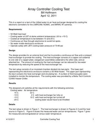
AD9826 ADC Preliminary Testing 1 • Fabricated small test PCB with same pinout as Analogic AD4322 (2MHz 16 bit) . • 2 PCBs tested in earlier version array controller. • Quick tests showed ~X3 gain vs AD4322s, but 11-12 ADUs Standard Deviation (range 9-12) in 1 channel Sample and Hold mode. • Data sheet says “3LSB” PGA=1 • PGA set =1, sampling freq ~5.6Mhz • Running Raytheon 206 multiplexer (3 ADUs STD nominal) • Tested with all 8 channels and image with Raytheon 206 mux to confirm signal gain and S/N.
AD9826 ADC Preliminary Testing 2 • Bench tested with precision voltage source, logic analyzer • 3 channel CDS mode has 0-1 ADUs STD. • PGA set =1, sampling freq ~1.9Mhz, AC coupled. • Device only wants Vreset more positive than Vsignal. • Test not valid if grounded input = 0 volts into ADC. • First/few? pixels bad. • NOAO results: • CDS and S&H modes have 7-8 ADUs noise @ 1.6usec • Removed 2nd stage premap stage = removed “capacitive charge effect”. None seen at IfA • “Note, apparently the AFE devices were designed to be used in a free running mode so that the capacitive effects relating to charging the AC coupling cap to the bias clamp voltage are eliminated.” Will investigate, IfA setup had different offset/clamp circuit. • Will retest next week to confirm results. • Samples of TI ADCs received.
Clocking Will build on previous (Redstar3) system VHDL design • 16,000 gate Altera FPGA EP6016 • 128kx16 Sync SRAM • Clocking FPGA • patterns • 7 x 1/48Mhz = 145.83nsec min pattern time • 1/48Mhz = 20.8333nsec pattern time extension • 10 bit pattern run length extension = 21.313usec • rows and frames 10 bit rep count = 1024 times • integration timer • 25usec time increments • 28 bit timer = 3.728 hrs max ITIME
Pixel server = Thin Server 1U rackmount PCs • Compaq Proliant DL360 G3 under test • Supermicro dual Xeon under test • Pixel servers in use on previous design with good results (faster than dual 32 bit 40MHz DSP system).
OTA Controller Power Supplies • HP 66000 System Power Supply, 8 modules/chassis • Each module has over voltage and over current protection • Simultaneous shutdown • Configured for simultaneous turn on and off • Proven low noise and safety performance on Mauna Kea (IRTF, SUBARU) • UPS run down and HELCO black/brownouts • Mechanical Specifications 19 inch rackmount • Width: 426 mm (16.75 in) • Height: 178 mm (7 in) • Depth: 678 mm (26.7 in)
Staffing Estimates • Needed: 5 FTEs estimated, plus use of Contract Manufacturers • 2 Electronic engineers (Onaka,TBD) • 2 Software engineers (Lockhart, Isani *) • 1 Electronic Tech (Ching) • Presently: 3+ FTEs on staff • 1 new EEI causal hire => direct hire position hire started • + 1 SE interviewing* • 1 EEII (with data comm, ISCSI ASIC/IC experience) in discussion • Contract Manufacturers (CM) for board assembly • Ching site visited 3 CMs. • IfA H85 AO 10 board run being sent through one CM as first run.
Production Plan • Two phase plan • Prototype phase • Use Contract Manufacturer (CM) for high density parts (i.e. BGA). • But obtain in house ability to rework - requires some infrastructure investment at IfA. • Contract out parts of electronics design that is “industry standard” (i.e. FPGA CompactPCI VHDL). • Production Phase • Use Contract Manufacturer (CM) to get quantity discounts. • Contract out design of automated test electronics. JTAG for digital? • Build multiple copies of low cost test station. • Have a conservative (high) spares count.
Lab Support/Infrastructure • In-house capability to do BGA rework. • BGA inspection microscope received training done. • BGA Xray microscope received training 8/8/03. • Previous Redstar2 and Redline controllers available for comparative measurements. • Switching CAD software to leverage new hire experience. • Protel to Cadence (for SPECCTRA router) • Cadence university donation request sent (with UH Physics). • Software download done, waiting for license. • Xilinx FPGA requires additional tools • Symplicity VHDL synthesizer received. • Mentor Modelsim simulation models on order (not received).
Development Task Breakdown Prototype Phase Basic Clock FPGA code Backplane design Clock Down load Trigger Dual OTA test Single OTA test Proto Interface Bd Component selection Centroid and shift Proto Chassis FPGA3U Proto FPGA3U Buy Dev Xilinx Board Interface to DAQ3U ADC read code Analog testing DAQ3U Proto DAQ3U Backplane interface Interface to FPGA3U Trigger design Analog Testing COTS CPU + 1G ethernet Centroid and shift Dev environment 1 G ethernet tests Multi OTA code Pixel Server Workstation 1 G ethernet tests Data Storage testing Data Export testing Centroid and shift Proto User Interface
Schedule Phase I End Goal: 4X1 OTA controller finished by Dec 2003 Hardware • Components selected Mid Aug. • PCB layout done = Oct. • Flex cabling finished Nov. • Controller prototype Dec-Jan. Software • 1 G ethernet throughput tested – Aug. • CompactPCI throughput tested – Aug. • Centroid/shift/load – Aug/Sept. • Pixelserver code – Nov. • OTA control development during Integration Oct-Dec.
Draft Workpackage Description Prototype Phase 1.0:Predesign 1.0.X • Workpkg 1.0.1 • Title: Location of OTA centroid/clocking generation. • Type: Study+test+decision • Description: • Combination study and test code generation for embedded PowerPC on FPGA vs. individual Pixelserver vs. top level Pixelserver. • Metrics: Appropriate centroid algorithm, speed of calculation vs collection, clocking pattern FPGA download and swtch time. • Estimate: 60hrs Software Engineer, 30hrs EEII. • Dependency: FPGA clocking VHDL code at testable level on ML300.
Draft Workpackage Description 2 Prototype Design workpackages: 1.1.X • Workpkg 1.1.1 • Title: Basic OTCCD clocking control • Type: Design+code+test • Description: Software code of clocking, test of download. Hardware design on ML300, schematic and VHDL for CAD input for PCB. • Metrics: OTCCD Sequenced readout functionality, speed. • Estimate: 60Hrs SE, 120hrs EEII, 80hrs SE*. • Dependency: none.
Workpackages Prototype Phase 1.0:Predesign 1.0.X Workpkg 1.0.1 Title: Location of OTA centroid/clocking generation. Type: Study+test+decision Description: Combination study and test code generation for embedded PowerPC on FPGA vs. individual Pixelserver vs. top level Pixelserver. Metrics: Appropriate centroid algorithm, speed of calculation vs collection, clocking pattern FPGA download and swtch time. Estimate: 60hrs Software Engineer, 30hrs EEII. Dependency: FPGA clocking VHDL code at testable level on ML300. Workpkg 1.0.2 Title: Number of FPGAs per controller. Type: Study+decision Description: Study of #FPGA I/Os + interboard connector vs. added power complexity of 2nd FPGA per controller. Metrics: Power consumption, PCB area available, connectors available, analog signal chain integrity. Estimate: 40hrs EEII. Dependency: none. Workpkg 1.0.3 Title: 1G ethernet from FPGA or embedded COTS CPU? Type: code+test+decision Description: Combination lab test of ML300 dev platform 1Ge throughput vs. PCI+COTS CPU (MENmicro). Metrics: Sustained throughput > = 64MBytes/sec Estimate: 60hrs Software Engineer,40hrs EEII. Dependency: none.
Workpackages 2 Workpkg 1.0.4 Title: Real CCD test of AD9826 ADC on Leach system Type: Design+fabrication+test Description: Design, fab and test AD9826 ADC on actual CCD to determine noise and speed performance acceptability. Metrics: Read noise spec = CCD and = data sheet at 1MSPS Estimate: 20hrs EEII remaining (ET hrs used also). Dependency: none. Workpkg 1.0.5 Title: Release 1.0 of requirements for controller Type: Design Description: Hardware and software requirements document. Metrics: Completeness, science and control goals. Estimate: 20Hrs SE, 20hrs EEII. Dependency: LAN/WAN interface, Telescope scheduler reqs. ------------------------------------------------------------------- Prototype Design workpackages: 1.1.X Workpkg 1.1.1 Title: Basic OTCCD clocking control Type: Design+code+test Description: Software code of clocking, test of download. Hardware design on ML300, schematic and VHDL for CAD input for PCB. Metrics: OTCCD Sequenced readout functionality, speed. Estimate: 60Hrs SE, 120hrs EEII, 80hrs SE*. Dependency: none.
Workpackages 3 see draft plan Workpkg 1.1.2 Title: FPGA PCB Type: Design+code+CAD+fabricate+test Description: Production of FPGA printed circuit board. Metrics: Power dissipation, size, speed of interfaces. Estimate: 40Hrs EEI, 60hrs EEII, ET estimate TBD*. Dependency: Predesign phase. Workpkg 1.1.3 Title: DAQ3U PCB Type: Design+code+CAD+fabricate+test Description: Production of DAQ3U printed circuit board. Metrics: noise performance at speed, size, power dissipation. Estimate: 40Hrs EEI, 60hrs EEII, ET estimate TBD*. Dependency: Workpkg 1.0.4. Workpkg 1.1.4 Title: Cryo flex/PCB Type: Design+CAD+fabricate+test Description: Production of rigid-flex cable assembly. Cyrotest integrity. Metrics: noise performance,size, vacuum performance, durability. Estimate: 40Hrs EEI, 30hrs EEII, ET estimate TBD*. Dependency: OTCCD pinouts final.