Download
1 / 44
440 likes | 557 Views
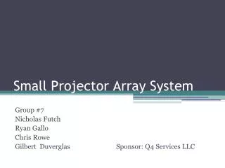
Small Projector Array System. Group #7 Nicholas Futch Ryan Gallo Chris Rowe Gilbert Duverglas Sponsor: Q4 Services LLC. Project Motivation Problems: High cost of current projector systems Degradation of image quality due to image warping Time loss due to image correcting

E N D
Small Projector Array System Group #7 Nicholas Futch Ryan Gallo Chris Rowe Gilbert DuverglasSponsor: Q4 Services LLC
Project Motivation Problems: • High cost of current projector systems • Degradation of image quality due to image warping • Time loss due to image correcting • Maintenance cost and time associated with lamp based projectors
Our Solution • Implement an array of low cost pico projectors • Lowers degradation of image due to the curvature of the screen • Internal image warping to save time on installs • LED projectors with extremely high life cycles
Specifications • Low cost solution • Easy implementation with existing simulators • Longer MTBF (Mean Time Between Failure) • Lower amount of pixel loss due to image warping
Graphics Cards AMD (formerly known as ATI) NVidia • Proprietary Crossfire Technology • Significantly better multi-monitor Support • Currently supports projector overlap • Warping and edge blending support soon • Proprietary SLI Technology • Slightly better overall Graphics
Projector Box Control System • Microcontroller system • Low power • Must accept RS-232 data from host computer • Must accept TTL data from the light sensor array • Digital outputs for control of various other parts
Schematic Atmega 328 microcontroller MAX232 chip for TTL to RS-232 signal conversion Two 2 to 1 Multiplexors to route Serial data to either the light sensor or the host computer system
Light Sensor Array Control System • Must accept TTL data from projector box • Must accept Analog signals from light sensor array
Schematic Atmega 328 Microcontroller 16 to 1 Multiplexor to switch between analog outputs Low pass filter for filtration of light sensor signals
Human Interface Specifications • Easy to use user interface • Ability to send data up to 50 feet • Independent interface for the light sensor array • Low power consumption • Cross-platform
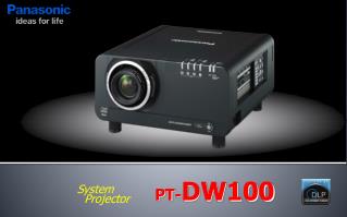
Projectors Specifications Requirements Solutions • Low Cost • High Pixel Count • LED • Low Power • High MTBF • High Brightness and Contrast • Low Noise • Variable Focus Control • Pico Projectors • 1280 x 800 Resolution • DLP LED • < 120 watts • 20,000+ lamp liftime
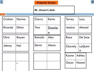
Projector Orientation and Overlap • The 4 projector layout with an aspect ratio of 1:1 • Resolution of 2600 x 1600 for a total of over 4.5M pixels • Almost identical to the latest WQXGA format at a fraction of the cost. • Will make the most use out of the usable area of the screen.
Analog Light Sensor • Used to get measurements from the single projector and the projector array for comparison. • Readings will be read by microcontroller and displayed on a GUI on the host computer
Light Sensor Specifications • PCB form factor no greater than 1in^2 • Low power consumption (less than .5 mW) • Max input voltage @ 5V (provided by microcontroller) • Analog output less than 5V • Range of illuminance between 0 and 100k lx • Maximum photosensitivity @ 550nm to mimic human eye
Opto hybrid(photodiode with an integrated circuit) Mimics the human eye almost exactly Very low power consumption Logarithmic current output(High accuracy over wide illumination range) Surface mount SFH 5711 by Osram
Light Sensor Circuit Diagrams • Illuminance: 0 - 10k lx • Output voltage: 0 - 3V
Light Sensor Array • Find a way to arrange light sensor in an array setup in front of projector screen • Must be easily stable, lightweight, and easily portable • Wires must not be obstructed so communication with projector box can happen • Solution: use a PVC pipe structures as array to house light sensors
ANSI Lumens Test • Describes the standard method for testing the brightness of projectors. • Method involves measuring brightness of a projector screen at 9 specific points using light sensors and finding average value between these points.
Light Sensor Array Testing • Warped image will be projected onto BP dome screen. • PVC light sensor array will be placed in front of screen facing projector box. • The wires coming from the array will be connected to the microcontroller in the projector box. • Lumens rating will be displayed on computer host system from each sensor and total lumens will also be displayed.
Light Sensor Array Considerations • Make array 3 x 6 instead of 3 x 3 so that array can cover and measure whole BP screen at once without physically moving array. • Automated light sensor array
Automatically move the PVC light sensor on top of BP projector screen Use of stepper motor and gears to apply rotational movement of array Clamp will be used to hold the array Array will be moved manually side to side to compare both projector systems Automated Light Sensor Array
Arduino Motor Shield Capable of driving one stepper Operates at 5-12V, 2A per channel 4A total Allows easy control for motor direction and speed Unipolar Stepper Motor Operates at 4V at 1.2A per channel Torque 27 lb/ft Motor and Motor Drive
Power System • Requirements: • Capable of powering following devices • 4 Pico Projectors (120 VAC) • 2 Microcontrollers (3.3 – 5 VDC) • 1 Servo Motor (4 VDC @ 2.4 A) • Host Computer System (120 VAC) • Power system should be capable of providing power to all these components from a single point or “power box” and only receiving the standard main power signal from a traditional wall outlet
Power System • Specifications • Input: Should be able to take incoming power signal from any outlet (100-240 VAC 50/60 Hz) • Output: Independent from incoming signal, will output regulated 3.3 – 5 VDC signal to microcontrollers and 4 VDC signal to servo motor, as well as remaining circuit components • Size: will be housed within the “power box” enclosure
Power System • Design Options: • 4 options considered that all met our power system design requirements.
Power System • Power Flow Diagram
Power System • Power Flow Diagram for components that require DC Power
Power System • KMS40-12 AC to DC Converter: • Input: 90-264 VAC • Output: 12 VDC • Current: 3.33 A • Power: 40 W • Type: Switching (Closed Frame) • Efficiency: 83% • Through Hole Board Mount • Load Regulation: ± 1%
Potential Issues • Alignment of Projectors • Single Stepper Motor torque • Sensitivity of Light Sensors • Overall Projected Image