Download
1 / 13
150 likes | 159 Views
HOME. DYNAPAC F1000T/W Paver Controller System. Propel Controller. Propel Controller - Specification. Start Up & Calibration. Download & Settings. Sauer Danfoss MC50-12 Integral Digital Signal Processor (DSP) with 256 K Flash memory

E N D
HOME DYNAPAC F1000T/W Paver Controller System Propel Controller
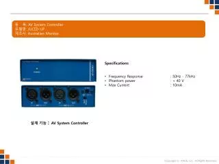
Propel Controller - Specification Start Up & Calibration Download & Settings • Sauer Danfoss MC50-12 • Integral Digital Signal Processor (DSP) with 256 K Flash memory • Application Development using Plus 1 Guide Software including service tool for function monitoring & controlling • 22 Inputs & 16 Outputs • 9 – 36V DC Power supply monitored internally • 2 CAN 2.0B Ports Click here for detailed spec.
Propel Controller - Inputs Console Select Switch Gear/Engine Speed Select Switch (0.5V to 4.5 V) Sauer DP200 Multi function Display (Connected Via CAN) Park Brake Switch Joystick/FNR Stick (0.5 V to 4.5 V) Steering Trim (0.5 V to 4.5 V) Max Speed (0.5 V to 4.5 V) LH Console Steering Wheel*** (0.5 V to 4.5 V) **Same Devices are repeated in RH Console *** Steering Wheel replaced by steering position sensor in F1000W
Propel Controller – Inputs contd • Speed Sensor ( Frequency Input) from LH, RH Propel Motor & Generator Motor • Fuel Sending Unit ( Resistance Input)
Propel Controller - Outputs • LH & RH Drive Pump – EDC control (15 to 85 mA) • Generator Pump – EDC Control ( 15 to 85 mA) • LH & RH Propel Motor Displacement Control ( Speed Shift) – Digital 24V • Planetary Gear Box Shift ( Digital 24V) • Console Select Relay output ( Digital 24V) • Automatic function ( Auger Conveyor, Vibration, Levelling system) enable relay (Digital 24V) • Fume Extractor Contactor enable output ( Digital 24V) • FWA Valve enable ( Digital 24 V) – F1000W only
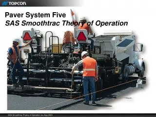
Propel System Control Layout Propel Controller • Joystick • Gear Selector • Speed Dial • Steering Wheel • Steering Trim • Dual path drive control system • Signal to LH & RH Propel Pump • Signal to propel Motor • Signal to Gear selector valve Speed Sensor Feed back Track Motor & Gear Box
Propel System Control Layout Speed Sensor Feed Back Commanded Input Commanded Input Speed Sensor Feed back
Propel System Layout Warnings/Active Faults • Propel Controller is built with the smartness of identifying any inputs or outputs connectivity or operator error while operating the Paver or any unwanted/un intended hazards. • If anything that happens abnormal then the propel controller will send a Warning Signal or Active fault to the Multifunction display (DP200) depending on the severity of the issue. • Warning Signal – This will be displayed if there is an un intended operation of the Paver & the signal will be no longer displayed once the paver function is operated correctly. • Example : Trying to give propel command when the park brake is engaged. • Active Fault – This will be displayed if there is improper wiring (Open or short circuit) or if the parameter’s goes out of limit than expected. This requires re-powering the entire machine after correcting the issue. The fault may continue to show up even after the re – powering if the issue still exists. • Example : Open/Short circuit on the Inputs/outputs. • Machine is not moving even after the proper command is given the pumps & motors. • Power supply issues • Improper wiring/grounding methods etc
Propel System Layout Warnings/Active Faults • List of Warning Codes Built In
Generator System Layout Propel Controller • Closed loop speed Control ( Frequency 60 Hz +/- 5% ) • EDC Control of S90 Generator Pump • Hyd motor to run @ 1800 rpm regardless of Engine/Generator load • PID (Proportional, Integral & derivative) Loop used • Signal to Gen Pump after 15 Sec of Engine Turn On • 15 to 85 mA Signal to maintain 1800 rpm of Motor regardless of engine speed & Gen load Speed Sensor Feed back Generator Motor
Other Systems • Automatic Function Turn on ( R7 Relay) • To allow the Automatic functions ( Screed Vibration, Auger conveyor system, Topcon Leveling system, Screed Float ) to activate only forward moving • Console Select Relay Activate • To active the LH & RH consoles based on the operator request based on pre determined conditions. • Fume Extractor Contactor enable • This o/p enables the fume extractor contactor with a delay of 5 sec after generator kicks on • FWA Valve Enable • To activate the FWA function only when the machine is moving forward & in 1st & 2nd gears only.
HOME Driven by innovation – committed to customer performance