Download
1 / 57
580 likes | 772 Views
Pan-STARRS Gigapixel Camera. An extremely audacious undertaking! Many IFA contributors (not to mention MIT Lincoln Lab): John Tonry, Gerry Luppino, Peter Onaka, Sidik Isani, Aaron Lee, Robin Uyeshiro, Lou Robertson, Greg Ching, Brian Stalder, Steve Rodney

E N D
Pan-STARRS Gigapixel Camera • An extremely audacious undertaking! • Many IFA contributors (not to mention MIT Lincoln Lab): • John Tonry, Gerry Luppino, Peter Onaka, Sidik Isani, Aaron Lee, Robin Uyeshiro, Lou Robertson, Greg Ching, Brian Stalder, Steve Rodney • Significant collaboration with WIYN observatory
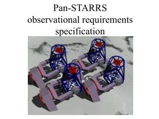
Astronomy & Astrophysics Decadal Survey Large Synoptic Survey Telescope (LSST) BUT: CCDs~8 Mpix, ~$80k 1¢ / pixel IR+Mux~4 Mpix, ~$0.4M 10¢ / pixel • 6-8m equivalent aperture • 7-9 square degree Field of View • 1-3 Gpixel detector The Panoramic Optical Imager (PanSTARRS) http://pan-starrs.ifa.hawaii.edu
Pan-STARRS Optical Design 1” 1/3 arcsec
Pan-STARRS Focal Plane • Need wide field (>3°) to meet science goals. • Desired psf sampling is <0.28” • Therefore we need >1 billion pixels per focal plane
Detector Enhancements • Increasing CCD yield will decrease cost • $ / device ~ ($ / lot) / (CCD yield / lot) • Decrease pixel size (but >8-10um to keep red QE) • $ / cm^2 means 10um is 44% the cost of 15 um • Remove image motion • 20% better psf equivalent to 56% better QE • Fast readout improves duty cycle (e.g. Suprime!) • Readout ~ sky noise dominance << saturation time • Reengineer CCD/cryostat/electronics/host computer with attention to costs and scalability
The Orthogonal Transfer Array (OTA) – A New Design for CCD Imagers • A new paradigm in large imagers OTCCD pixel structure OTA: 8x8 array of OTCCDs Basic OTCCD cell
DetectorDetails – Overview Each CCD cell of a 4Kx4K OTA • Independent 512x512 CCD • Individual or collective addressing • 2-3 arcmin field of view • Dead cells excised, yield >50% • Bad columns confined to cells • Cells with bright stars for guiding • 8 output channels per OTA • Fast readout (8 amps, 2 sec) • Expect >90% fill factor despite inter-cell gaps, dead cells, and inter-OTA gaps; four telescopes and dithering fills in the gaps. 5cm 12 um pixels
Increasing CCD yield • Wafer yields and thinning yields tend to be good, • Primary cause of dead devices is catastrophic, local defects such as gate to substrate shorts or bad amplifiers. • Packaging and metrology dictates against very small devices (< 2K). • A 25% yield of a 2K x 4K CCD implies ~0.1 defect per cm^2 on average. • Need a way to isolate defects without losing the device.
OTA “Array” Strategy has other Benefits • Independently addressable cells allow on-chip guiding. • Independently addressable cells offer some immunity to the effects of very bright stars. • Bleeding tails or bad columns from bright stars are confined to the cells that contains the stars. • E.g. Image at right shows a 9th magnitude star with the green grid illustrating the size of the OTA cells. We expect approx 15 stars of this brightness or greater in each PanSTARRS field.
Fast Readout • Near Earth objects move one psf width in 30 sec • Therefore we gain no additional S/N beyond ~30 sec exposures, making ~2 sec readout desirable. • 1 Mpixel/sec per amplifier with 4 e- read noise is achievable but requires care (faster contributes more noise than sky). 3 minute exposure of NEO • Must have many amplifiers • 1 Gpix in 2 sec at 1 Mpix/sec requires 500 amps and signal chains! (Example: CFH Megacam uses ~80 amplifiers, 200 kpix/sec, 20 sec readout.)
Remove Image Motion • Tip-tilt plate or mirror • Limitations on size and speed • Ghosts from transmissive tip-tilt plate • Full-field correction only • Atmospheric motions • Decorrelate at some angle between 1 and 10 arcmin • Amplitude comparable to seeing (removal of all image motion improves net image size by about 20%). ISU from CFH Megacam
The Orthogonal Parallel Transfer Imaging Camera • A 4K x 4K camera (10 arcmin • FOV) capable of electronically • removing image motion via • orthogonal transfer at rates up to 100 kHz and capable of tracking and recording guide stars at rates up to 100 Hz. • MITLL CCID-28 • 2Kx4K CCD • Four-side buttable package • Four independently clockable regions per chip • Orthogonal Transfer pixels
OPTIC • Two CCID-28s adjacent to each other • Four lower parallel regions "guide regions" • Four upper parallel regions "science regions" • SDSU-2 electronics, Four video channels, 4e- noise at 125kpix/sec 4096 10' 4096 Tracking/guiding Operation 1.Read out small patch around 1-4 guide stars 2.Centroid; apply prediction and interpolation 3.Apply shifts to science regions 4.If exposure not elapsed, goto 1.
OTCCD Performance: Lab Tests • In “stare mode” (clock only on readout) CCID28’s are perfectly good CCDs • CTI measured at 2E-6 serial and parallel • Noise is 3.5-4.0 e- at 1 usec integration (500 kpix/sec) • Dark current at –90 is far below sky in broad band filters • Full well is at least 80k e- • Linearity is at better than 2% to 50k e- • No fringing in I band, a few percent in Z band • QE is good – typical for IILA backside process.
OTCCD Performance On Sky • Astrometry (Monet) • 1-D fit at 8 mas, 2-D fit at 5 mas: no problems with OT pixels • Photometry (Howell) • “we expect tht the OTCCDs used by Pan-STARRS will be able to provide relative photometric precisions of better than 2 mmag rms…” • Photometry (Saha) • OT pixels perform as well as 3-, variations in psf from OT tracking do not hinder photometry. • Science (Chambers) • “Image quality is always superior, and we have obtained the best optical images ever achieved with the 88-inch (0.45 arcsec FWHM in R band) .” • “Flat fielding is at least as good as 1 part in a 1000.” U gem OT vs std OT vs true N2419
Orthogonal Transfer • Orthogonal Transfer A new pixel design to noiselessly remove image motion at high speed (~10 usec) Normal guiding (0.73”) OT tracking (0.50”)
Guided Image Motion 0.33"FWHM 0.32"FWHM Star #4 (8') Star #3 (2') Star #2 (8') Star #1
Differential Image Motion 0.16"FWHM 0.18"FWHM Star #4 (8') 0.12" FWHM 0.10"FWHM Star #3 (2') 0.16"FWHM 0.18"FWHM Star #2 (8') Star #1
Camera Software – Observing Loop Receive coords Choose GS Exposure complete? Integrate on GS Apply OT shifts Temporal prediction for next GS position Read out cells Read GS subarray Guide telescope Quick look Tweak tel? Spatial prediction for cell’s motion Erase CCD Open shutter Send data to pipe Centroid & flux GS Update display
Camera Software – Existing Code • OPTIC software • “Eight cell” OTA • Four guide stars • Complete system: • DSP code • Interface/device driver • Camera control • Analysis/prediction • Graphical User Interface • 100 Hz on 1GHz host
Lot 1 Wafer Layout • Four versions of OTA and wafer splits • Different pixel sizes (12 µm vs. 10 µm) • Pixel layout (Type 1 vs. Type 2 OT) • Metallization variations to improve yield and fill factor • Deeper depletion via substrate bias • CMOS hybrid option • Miniature OTA (MOTA) • 22 array of cells • Several versions to explore higher risk but highly desirable new features • 2-phase serials • Gated amplifier
Pixel structure OTA: 8x8 Array of Cells Independently Addressable Cell OTA Lot 1
Detector Details – Clock and Analog Signals and Cell Addressing Control circuitry for parallel clocks Control circuitry for multiplexing video outputs
330 µm 180 µm Physical Layout of OTA Logic • Approximately 40 MOSFETs (nMOS) • Area ≈ 0.06 mm2 ≈ 400 pixels (<0.15% of OT cell) • Power dissipation~5 mW is somewhat high; lower power alternatives under study • Layout verified for functionality and performance using standard CAD tools
OTCCD On-Telescope Testing Summary • Mauna Kea has median seeing of 0.3” at altitudes above 500m, lower turbulence has very wide isokinetic angle • Seeing in excess of 0.3” is almost always highly correlated over angles of greater than 10 arcmin • At the north galactic pole each 10 x 10 arcmin area • has one star at R < 12.5 on average; • an OTA subtends four times this area. • Nominal guiding strategy • use all stars with R < 12.5 for guiding, • 4 per OTA, 240 per focal plane, • linear interpolation of guide star positions used to correct each cell’s location, • median residual image motion should be less than 0.2” FWHM.
OTA Pinouts • OTA realization • Pinouts defined • Package in fabrication • Connectors identified • Flexprint being designed • Cryostat feedthrough • Connections to controller
OTA Package Wirebond Ceramic • Details of Multilayer Ceramic PGA • Internal 3 routing layers plus groundplane to isolate digital from analog layers. • Includes space for temperature sensing diode attached to ceramic.
OTA Package Details OTA die Moly Frame, Mounting Feet and Alignment Pins Multilayer ALN Ceramic PGA Flexcircuit
OTA Handling Mount • Mount designed for rapid and safe handling of OTAs during testing phases.
Four-OTA Module 4-OTA Flexcircuit Controller Electronics
Eight-OTA “Bars” = Focal Plane Row 1 Bar 2 Bars
Electronics – Signal Chain • SDSU dual channel video board • 2 channels • 150 kpixel/sec • CDS, 16 bit ADC • 15 W power • Analog Devices 9826 • 3 channels (RGB) • 15 Mpixel/sec • CDS, 16 bit ADC • 250 mW power
PREAMP OUTPUT 4 PEDESTAL SAMPLES @120nsec 4 SIGNAL SAMPLES @120nsec ADC9826 Testing • Extensive testing with prototype daughterboard mounted on modified Leach system. • CCID20 performance adequate with multiple sampling and digital subtraction. • ADC9826 = 2.1ADU Read Noise with (4 signal samples – 4 pedestals)/4 at 1.2usec per pixel. Linearity good to 1%. • Leach Datel ADC937 = 2.33ADU Read Noise, at ~4usec/pixel.
Completed CAD DAQ3U_proto • 14 layer PCB • 50 Ohm controlled impedance stackup • Matched length on critical connections • 672 and 74 ball BGAs
IOTA Controller • SDSU controller • 8 channels = 1 OTA • 500 kpix/sec • 100W power • IOTA controller • 16 channels = 2 OTA • 1000 kpix/sec • 25W power
DAQ3U = 100mm 160mm PCB slot pitch = 20.32mm 5 SLOTS = 101.6mm DAQ3U PREAMP PREAMP PREAMP DAQ3U DAQ3U DAQ3U Prototype Design for 1x4 OTA Controller OTA OTA OTA OTA Flexprint PCB PREAMP JTAG PGM CPCI/CUSTOM backplane 100BT switch Pixelserver PC 1U
(Quad OTA building block, 8K x 8K “host computer unit cell”) Electronics – Building Blocks QUOTA
IOTA3U controller operates 4 OTAs For a 8 x 8 OTA focal plane, 2 rows of 1 x 8 OTA’s Each row has 8 IOTA3U controllers. OTA OTA OTA OTA OTA OTA OTA OTA OTA OTA OTA OTA OTA OTA OTA OTA OTA OTA OTA OTA OTA OTA OTA OTA OTA OTA OTA OTA OTA OTA OTA OTA OTA OTA OTA OTA OTA OTA OTA OTA OTA OTA OTA OTA OTA OTA OTA OTA OTA OTA OTA OTA OTA OTA OTA OTA OTA OTA OTA OTA OTA OTA OTA OTA IOTA3U IOTA3U IOTA3U IOTA3U IOTA3U IOTA3U IOTA3U IOTA3U IOTA3U IOTA3U IOTA3U IOTA3U IOTA3U IOTA3U IOTA3U IOTA3U LAN Switch 1Gb ethernet Fiber isolated Pixel Server Pixel Server Pixel Server Pixel Server Pixel Server Pixel Server Pixel Server Pixel Server Pixel Server Pixel Server Pixel Server Pixel Server Pixel Server Pixel Server Pixel Server Pixel Server Power Supply 2-row OTA Controller “Rack” 1Gb ethernet
Computer Cluster and Pipeline • Sixteen QUOTAs, (32K x 32 K) times 4 telescopes Four 4Kx4K OTAs, controller, Gbit fiber One CCD host and pipeline computer • Synchronized readouts, shared guide star info, common pipeline. • 8 Gbyte per minute, 10 Tbyte per night, 3 Pbyte per year. • Host computers organized by field of view.
Four OTAs in Test Cryostat • Simultaneous testing of 4 OTAs. • Cooling with a single IGC-Polycold Cryotiger. Cryotiger can mount on side plate or on back plate. • Flexcircuit perforate cryostat wall on two sides. • Simple and safe device installation and removal. All access from the front. • Room on focalplane for additional components (e.g. calibrated photodiodes).
Four OTAs in Test Cryostat Focalplane • OTAs mounted on pitch to be used in GPC. • Gap size equals one OTA width. • Allows accurate prototyping of internal flexcircuit. 4-OTA flexcircuit: 2 positions used for device testing