Download
1 / 41
490 likes | 811 Views
The Sensor Project. Motor “Direction” together with sonar. Left motor. Table of Contents. I. Introduction 2 II. Positioning System 2 III. Sensory System 3 IV. Project Goal 4 V. Selecting The System 4 VI. Program The Brick 5 VII. Building The Robot 6 VIII. Project Code 7

E N D
Motor “Direction” together with sonar Left motor
Table of Contents • I.Introduction 2 • II.Positioning System 2 • III.Sensory System 3 • IV.Project Goal 4 • V.Selecting The System 4 • VI.Program The Brick 5 • VII.Building The Robot 6 • VIII.Project Code 7 • IX.Performance Result 13 • X.Future Improvements 14 • XI.Conclusion 15 • XII.Reference 15 • XIII.Appendix 16
Our first task – mapping and navigation • The general problem of mobile robot navigation has to answer three questions: • “Where am I?.” • “Where am I going?,” • “How should I get there?.” • Our project will focus on how to achieve these three main questions using a mobile robot system and at the same time map its surroundings. • In order to answer the first and most fundamental question: “Where am I?,” the system requires some sort of build-in sensing equipments to position itself.
Positioning System • Most common positioning system in robotic divides into two categories: relative and absolute position measurements and the brief description shown below: • The Relative Position Measurements • Uses internal sensor to measure its distant traveled relative to the previous position. • The advantage is that it’s totally self-contained and does not need any external system support to locate its position. • On the other hand, its position error grows without bound unless and independent reference is used periodically to reduce the error. • Two types of sensory system shown below are typically used for relative position measurement.
relative position measurement. Two types of sensory system shown below are typically used for relative position measurement. Odometry – This method uses encoders to measure wheel rotation and/or steering orientation. Inertial Navigation – This method uses gyroscopes and accelerometers to measure rate of rotation and acceleration.
Absolute Position Measurements • The Absolute Position Measurements is using a “known” external environment to locate its absolute position in the map given like the global positioning system (GPS). • The advantage is that it can navigate through the environment accurately. • The disadvantage is that: • the location of source signal must be known • or a detailed map of the environment must be given. • There are few different types of system is using the absolute position measurement which are shown below
Absolute Position Measurements • Active Beacons – • The robot computes its position from measuring the direction of incidence of three or more actively transmitted beacons. • The transmitting signal could be light or radio frequencies. • Artificial / Natural Landmark Recognition – • The robot identifies the landmark (artificial or natural) with a recognizable feature • This feature is preset in the system to position itself in the known map. • Model Matching – • it is a complex matching system which identifies its surroundings with its internal map and world model of the environment to estimate its position. • This is a more high level system • It can: • improve global maps based on the new sensory observations in a dynamic environment • Integrate local maps into the global map to cover previously unexplored areas.
Project Goal • Build a mobile robot using some of the sensory and compute method described previously to perform desired tasks. • In this project we focus on two main goals: • obstacle avoidance • environment mapping. • The robot needs to be able to: • navigate at an unknown environment, • stop when there is an obstacle in the desire path, • avoid the obstacle by changing route, • map the environment without outside influence.
Limited system capability • The NXT programmable microcomputer, so called the Brick. • It has an Atmel 32-bit ARM7 processor with 256KB Flash memory, 64KB RAM, and a speed of 48 MHz. • The Brick also come four sensor inputs, three motor outputs connection, USB connection, LCD display with four bottoms controller, a loudspeaker, and Bluetooth capability.
Our use of motors • The Servo Motor – it uses a built-in incremental optical encoder to precisely control the motor’s output. • The NXT allows to specify the rotating degree with an accurate of one degree, the rotating revolution, or run time at different output powers. • The user can also synchronize between two motors and control using other internal readings.
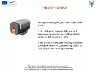
Our use of sensors • The Ultrasonic Sensor – as described previously allows the robot to measure distances to its surroundings and avoid obstacles. • The NXT ultrasonic sensor has a range of 255 cm and accuracy within 3 cm.
Programming in NXC • The most common C like compiler for NXT are RobotC and NXC (Not eXactly C). • Since the RobotC requires license to use, the project robot was coded in NXC, which is an open source compiler • The NXT has a bytecode interpreter, which can be used to execute programs. • The NXC compiler translates a source program into NXT bytecodes, which can then be executed on the target itself. • Although the preprocessor and control structures of NXC are very similar to C, NXC is not a general-purpose programming language, and there are many restrictions that stem from limitations of the NXT bytecode interpreter. • The lexical rules of the compiler and the NXT input/output reading commands can be found at the “NXC Guide”.
Project Code • The project code was written based on the concept of answering the three fundamental questions • Where am I, • Where am I going, and • How should I get there and meeting the project goal at the same time. • The answer for those questions would be : • “The robot is sitting on a [x,y] coordinates which start with [0,0] • and always moving forward • with tracking of orientation and distance on the best path which was decided after obstacles detection.”
Calibration function “Distant_Check” Calibration function“Distant_Check” ********************************************************************* The program checks the speed of the robot at given surface and battery life. ********************************************************************* The program starts with defining the ultrasonic sensor, input port 4, and driving motor as output port A & C. Integers dist1, dist2, dist_avg, i defined. ------------------------------------------------------------------------------- #define US SENSOR_TYPE_LOWSPEED_9V //define US as the Ultra Sonic sensor #define Motor OUT_AC //driving motor #define US_IN IN_4 //US sensor input task main() { int dist1; int dist2; int dist_avg; int i; -------------------------------------------------------------------------------
This section set ultrasonic sensor in input port 4 and with a little time delay (0.05 seconds). Initiate counter i to 0. ------------------------------------------------------------------------------- SetSensorType(US_IN, US); // US sensor in input port 4 Wait(50); i = 0; ------------------------------------------------------------------------------- This section show the ultrasonic sensor will take distance reading 1 second apart for 5 seconds and average the distance which is stored in dist_avg. ------------------------------------------------------------------------------- while (i <5) { dist1 = SensorUS(US_IN); OnFwdSync(Motor,50,0); Wait(1000); dist2 = SensorUS(US_IN); if(i == 0){ dist_avg = (dist1-dist2); } else { dist_avg = (dist_avg+(dist1-dist2))/2; } i++; } ------------------------------------------------------------------------------- Two measurements to make average
This last section of task maim outputs dist_avg on the NXT LCD screen until the user cancels the operation --------------------------------------------------------------------- while (true) { Off(Motor); NumOut(0, LCD_LINE2, dist_avg); } } --------------------------------------------------------------------- End of task main is here
“Rotation_Check” Calibration function “Rotation_Check” ********************************************************************* This program checks the rotation angle on the given surface and between left and right motor. It is used only for calibration *********************************************************************
The section of task main defines the left and right motor and integer i. --------------------------------------------------------------------- task main() { #define R_Motor OUT_A #define L_Motor OUT_C int i; ---------------------------------------------------------------------
rotate the robot left for 4 times ------------------------------------------------------------------------ The following section will rotate the robot left 4 times with 45 degree each and next do the same rotating the robot to the right. ------------------------------------------------------------------------------- i = 0; while(i < 4) { RotateMotor(R_Motor,50,135); Off(R_Motor); Wait(800); i++; } i = 0; while(i < 4) { RotateMotor(L_Motor,50,135); Off(L_Motor); Wait(800); i++; } } ---------------------------------------------------------------------- End of task main
Main function “Mapping_Bot” • This is the main program for the project • It creates the output data file • It calls all the subroutines with user defined repeated number of times. • The robot will run for 5 seconds, and at the same time perform obstacle avoidance task and robot orientation for each second. • After 5 seconds, the robot will sweep the surrounding from -90 to 90 degrees. • Finally calculate its position and output robot position and sweeping result into the text file “Result.
MAIN The program includes “My Position.nxc” which has all the subroutine codes. Defines function for ultrasonic sensor #include "My Position.nxc"; task main() { string header; SetSensorType(US_IN, US); // US sensor in input port 4 Wait(50); obstacle() scan_record() position()
Creating new file name “Result.txt” and output “Mapping“ if success else output “Error” on the NXT LCD. • The orientation of the robot is set to 90 degree which is the +Y direction. • Function in the middle calls all the subroutines with user defined repeated times. • The file is closed after all the subroutine is done, and it is ready to be exported out through USB or Bluetooth • Obstacle avoidance • Scan record • Position calculation if (CreateFile("Result.txt", 2048, handle) == NO_ERR) { TextOut(0,LCD_LINE2,"Mapping"); x = 0; y = 0; orit_d = 90; //preset to 90 degree, assume robot faces the +Y direction header = "[X, Y]cm [-90, -60, -30, 0, 30, 60, 90]degree"; WriteLnString(handle, header, bytesWritten); repeat (7) { obstacle(); scan_record(); position(); } CloseFile(handle); } else { while(true) { TextOut(0,LCD_LINE2,"Error"); } } } // end of task main
Obstacle Avoid Subroutine function “Obstacle Avoid” ********************************************************************* The subroutine checks for obstacle within 30cm in the front of the ultrasonic sensor. The robot continues straight if no obstacle found, else finds the best path by checking distance to 40 degree to the left and right. Pick direction with longer path and rotate the robot 45 degree to that direction then continue straight if no obstacle found. ********************************************************************* The program start with define motor and sensor name and ports. Different integers are setup for the program to use, see common for each in detail. ------------------------------------------------------------------------------- #define Motor OUT_AC //driving motor #define R_Motor OUT_A //Right driving motor #define L_Motor OUT_C //Left driving motor #define US SENSOR_TYPE_LOWSPEED_9V //define US as the Ultra Sonic sensor #define US_IN IN_4 //US sensor input #define Direction OUT_B //US sensor and driving direction motor #define rotate_angle 45 //angle rotated per term int opst; //distant to obstacle int left; // 40 degree to the left int right; // 40 degree to the right int RunTime; // total run time int run; //straight run time int orit[5]; //vector to record the orientation, size=5 int i_orit; // count for orientation int orit_d; //orientation in degree -------------------------------------------------------------------------------
Start the subroutine, set initial value for i_orit to 0 (this is the main counter for the subroutine) i_oritis incremented for every 1 second the motor run forwards. The subroutine will run for 5 seconds and record the orientation it run in for each second then stop. If no obstacle within 30 cm, the robot will continue to run forward until i_orit count reach 5. sub obstacle() { RunTime = 0; i_orit = 0; while(i_orit < 5) { opst = SensorUS(US_IN); //read US value run = 1000; //set motor to run 1 sec if(opst > 30) //check if obstacle within 30cm { OnFwdSync(Motor,50,0); //continue FW if no obstacle Wait(run); //run 1 sec RunTime += run; //calculate total run time orit[i_orit] = orit_d; //set orit[] in it's orientation i_orit++; }
If there is obstacle within 30 cm, the robot will stop and check distance +/- 40 degrees from center and store the distant in int left & right. left and right is compared for the best path (larger distane) and the robot will turn 45 degree to that direction with the help of front steering wheel trying towards the best path and then +/- the orientation angle by 45 degrees. else{ Off(Motor); //stop motor if obstacle found //check best path RotateMotor(Direction,50,-40); left = SensorUS(US_IN); RotateMotor(Direction,50,80); right = SensorUS(US_IN); if(left < right) //pick best path (left or right) { RotateMotor(L_Motor,50,135); //rotate 45 degree to the right RotateMotor(Direction,50,-40); orit_d -= rotate_angle; //decrease orientation by 45 degree } else{ RotateMotor(Direction,50,-80); RotateMotor(R_Motor,50,135); //rotate 45 degree to the left RotateMotor(Direction,50,40); orit_d += rotate_angle; //increase orientation by 45 degree } } } Off(Motor); } // end of sub obstacle
SUBROUTINE Dist Track The subroutine perform distant scan from -90 to 90 degrees with 30 degree interval after every 5 second of the robot movements. The result of the scan is store in the string “dist_record”. ********************************************************************* First section defines all the sensor and motor same as other program and some variable will be used in this program. ------------------------------------------------------------------------------- #define US SENSOR_TYPE_LOWSPEED_9V //define US as the Ultra Sonic sensor #define Direction OUT_B //US sensor and driving direction motor #define Motor OUT_AC //driving motor #define US_IN IN_4 //US sensor input #define R_Motor OUT_A //Right driving motor #define L_Motor OUT_C //Left driving motor int dist; // distance of the US sensor in cm int scan_ang; //set scan angle byte handle; short bytesWritten; string dist_result; //result of distance from -90 to 90 degree
Check if motors stoped • The subroutine will check if all motor is stop, if so, scan angle will start from -90 degrees. • And while the scan angle is less than 91 degree the ultrasonic sensor will read the distant 3 time and take the average before increment the scan angle by 30 degrees. sub scan_record() { int i, dist1, dist2; //start checking distant if both left and right motor are off if(IOMA(OutputIOPower(R_Motor)) == 0 && IOMA(OutputIOPower(L_Motor)) == 0) { scan_ang = -90; //initial value to -90 degree RotateMotor(Direction,50,scan_ang); while(scan_ang < 91) //scan and record until it finish for 180 degrees { i = 0; dist1 = SensorUS(US_IN); //measure distant while (i <3) //scan for 3 times and average the result { dist2 = dist1; dist1 = SensorUS(US_IN); //measure distant dist = (dist1+dist2)/2; i++; }
The distant average reading from the ultrasonic sensor is store into a string called dist_result. • Due to the desired format for the string as [x,x,x,x] cm, the string is composed by 3 if statements for the first, middle, and last reading shown in this section of the code. //store value string "dist_result" string dist_s = NumToStr(dist); if(scan_ang == -90){ RotateMotor(Direction,50,30); //rotate direction to match scan angle dist_result = StrCat(dist_s,", "); } if(scan_ang < 90 && scan_ang > -90) { RotateMotor(Direction,50,30); //rotate direction to match scan angle dist_result = StrCat(dist_result,dist_s,", "); } if(scan_ang == 90) { RotateMotor(Direction,50,-90); //rotate direction back to front dist_result = StrCat("[",dist_result,dist_s,"] cm"); } scan_ang += 30; //increment scan angle } } } // end of subroutine scan_record
Subroutine My Position This subroutine combines the result of robot orientations from “Obstacle Avoid” and mapping data from “Dist Track” to calculate the robot position and create the final output string that will be export out later. The subroutine also have control over the define speed for the robot to generate a more accurate positioning. First section of the code includes the previous two subroutines to be able to use data collected during those subroutines. This program also defines the SPEED of the robot, which got it from the calibration program “Distant_Check”. Other variables such as x, y, and output string write also are defined in this section. ------------------------------------------------------------------------------- #include "Obstacle Avoid.nxc"; #include "Dist Track.nxc"; #define speed 11 // robot move 11 cm straight per second int x; int y; string location; string write; -------------------------------------------------------------------------------
This part calculate the position of the robot in the [x,y] coordinates using the speed and the orientation of the robot combine with the trig functions to extract the x and y components. sub position() { i_orit = 0; while(i_orit < 5) { orit_d = orit[i_orit]; x = x+speed*Cos(orit_d)/100; y = y+speed*Sin(orit_d)/100; i_orit++; }
This combines the location of the robot with the surrounding sweeping result into a single string “write” and writes it into the file “Result.txt” string x_s = NumToStr(x); string y_s = NumToStr(y); location = StrCat("[",x_s,", ",y_s,"]"); write = StrCat(location, " ",dist_result); //store value in file - Result.txt WriteLnString(handle, write, bytesWritten); } //end of position subroutine
Performance Result • After all the hardware and software modification, the robot is able to perform the two main objective of this project, which are obstacle avoidance and environment mapping. • Of course there are some limitations due to the simplicity of this prototype mobile robot system such as the viewing angle of obstacle avoidance and the surface condition depending performance. • Although with the system limitation, the output raw data from the robot shown below are actually as expected. • There is still some more data analysis needed to generate the mapping of the environment to know the accuracy of the system. • Overall, under a fixed and well-designed environment, the performance of the robot is great. • Next section will discuss some of the issue the system ran into on an unknown environment and how to improve the system’s robustness.
Future Improvements • There are four main areas that the current system can be improved in the future, and this section is going to explore some the possibilities. • 1. Communication: • The Bluetooth function of the NXT has not been fully explored and used by the current system. • The goal for the future is to be able to have real time communication between the computer and the NXT. • The data can be feed back once every cycle and perform real time mapping on the computer. • Build communication link between NXT and plotting software such as MATLAB and MRPT. • Real time commands to order the NXT to a previous mapped spot.
2. Robot Stability: • Rebuild the current three wheels system into a four wheels system to ensure the traveling direction • the present system sometimes would curve to the left. • Some sort of gear system either between front and back wheel or front wheel and ultrasonic sensor could be established. • Error diction and correction using the internal motor sensory to compensate the external hardware weakness.
3. Obstacle Avoidance Algorithm: • Create a feedback loop from the environment sweep with the best path selection to give a better avoidance algorithm. • The current system can only detect obstacle in front of it but not side ways and sometimes it will get stuck in a corner. • Some kind of reverse path algorithm when the system get stuck, • but this also need to be combined with the current position algorithm.
4. Mapping Algorithm: • Currently the system only maps the environment every 5 seconds. • The future system will have to map more frequently to provide a faster feedback. • To build the ultrasonic sensor similar to a radar: • The sweeping speed will be synchronized with the driving motor • that way the current positioning algorithm can be used.
References • “Where am I? Sensors and Methods for Mobile Robot Positioning”, J. Borenstein, University of Michigan • “A Sonar-Based Mapping and Navigation System”, Alberto Elfes, Carnegic-Mellon University • “Real-time Obstacle Avoidance for Fast Mobile Robots”, J. Borenstein • “The Unofficial LEGO Mindstorms NXT Inventor’s Guide”, David Perdue • http://babel.isa.uma.es/mrpt • http://bricxcc.sourceforge.net • Http://mindstorms.lego.com • http://nxtasy.org