Download
1 / 21
210 likes | 390 Views
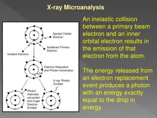
Narrow plasma & electron injection simulations for the AWAKE experiment. A. Petrenko, K. Lotov, October 11, 2013. 1. Narrow plasma simulations. Baseline simulation from CDR (4 mm wide plasma):. 2 mm wide plasma (r = 1 mm):. 2. Plasma electrons. Proton beam.

E N D
Narrow plasma & electron injection simulations for the AWAKE experiment A. Petrenko, K. Lotov, October 11, 2013 1
Narrow plasma simulations Baseline simulation from CDR (4 mm wide plasma): 2 mm wide plasma (r = 1 mm): 2
Plasma electrons Proton beam Electrons start to leave plasma after SMI develops: Single particle trajectory: Large Er 200 keV/cm (20 MeV/m) 3
Plasma section entrance After 1 m: After 2 m: Electron energy = 15 MeV Electron beam transport parallel to plasma/proton beam Close-up of Er field map: Electron beam is too sensitive to small fields over long distances. Even small numerical noise-level Er completely destroys parallel electron beam over 2 m distance. It is very difficult to calculate Er outside plasma with enough accuracy for accurate beam transport simulation. Just some very small noise Er 4
Initial beam configuration: 15 MeV electron beam Metal screen (first 6 m) protons plasma Energy of electrons after 1.2 m: Plasma wave acceptance xi-r & xi-r’ acceptance: 5
n(Rb) = 0 5 m of plasma section 15 MeV electron beam with realistic emittance (εn = 2 mm*mrad) In the middle of plasma section (5 m): In vacuum n(Rb) = 1015 cm-3
Electron beam after scattering vs plasma wave acceptance Beam r·pϕ distribution: r-r’ acceptance: r·pϕ acceptance: 9
(Baseline variant) 10 Np = 3.0e11 2.2 % of e-beam is captured
11 Np = 3.0e11 1.1 % of e-beam is captured
12 Np = 3.0e11 1.1 % of e-beam is captured
13 Np = 3.0e11 0.6 % of e-beam is captured
(Preliminary) Effect of dipole magnetic field on side-injection dipole 50 MeV e- 50 MeV e- L = 20 cm, B = 70 Gs 14
Conclusions • Large number of electrons are ejected from plasma as a result of SMI (may be useful for diagnostic of SMI). • Metal screen between electron and proton beam/plasma will probably be required for electron beam transport inside plasma section. • Typical injection efficiency with realistic 15 MeV e-beam is 1-2 % • (Preliminary) Dipole magnetic field (approx 50 Gs) at the injection point increases the side-injection efficiency and makes it possible to inject higher-energy electron beam (50 MeV for example). 15
17 Transverse acceptance 17
18 e-beam 15 MeV Angular momentum acceptance For r = 3 mm: r*pϕ is conserved 18
19 Energy acceptance 19
20 In vacuum: n(Rb) = 1015 cm-3: 20
21 Metal screen 2 mm wide channel Fast valve Options for electron transport line Difficult to simulate (though may actually work) Easier to simulate, should work, but the number of captured electrons will probably be reduced due to scattering on neutral gas (which induces large r*pϕ) The best control over beam parameters, and the best capture efficiency, (with longitudinally compressed beam might be possible to capture all electrons). 1 m 21