Download
1 / 13
130 likes | 239 Views
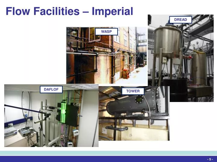
Flow Facilities – Imperial. DREAD. WASP. DAFLOF. TOWER. - 5 -. DREAD. Drag Reduction Experiments and Diagnostics. - 6 -. DREAD. Drag Reduction Experiments and Diagnostics. Water. F. Pressure driven system for drag reduction characterisation

E N D
Flow Facilities – Imperial DREAD WASP DAFLOF TOWER - 5 -
DREAD Drag Reduction Experiments and Diagnostics - 6 -
DREAD Drag Reduction Experiments and Diagnostics Water F • Pressure driven system for drag reduction characterisation • Homogenous and heterogeneous drag reduction testing • Single phase flow as well as liquid-liquid multiphase flow • Non-intrusive gross flow measurements • Differential pressure • Flow-rate • Turbulence characterisation • PIV • Parameters • 8 m long test section • ID = 25.3 mm • Remin = 10,000 • Remax = 1,000,000 Compressed air MT Differential pressure transducers Valves P CMOS camera DT PV T H Drain F Vis cell Drain Nd:YAG laser Drain PIV acquisition PC Control panel Data acquisition PC - 7 -
DAFLOF Downward Annular Flow Laser Observation Facility - 8 -
DAFLOF Downward Annular Flow Laser Observation Facility • Downward gas-liquid multiphase flow characterisation • Time-resolved LIF and PIV • Controlled parameters • Flow-rate • Temperature • Differential pressure • Parameters • 3 m long test section • ID = 32 mm • Regasmax = 75,000 • Reliquidmax = 1,300 - 9 -
TOWER Two Phase Oil Water Experimental Rig - 10-
TOWER Two Phase Oil Water Experimental Rig BV14 BV16 • Horizontal liquid-liquid multiphase flow characterisation • Time-resolved LIF and PIV • Controlled parameters • Flow-rate • Temperature • Differential pressure • Inlet conditions BV17 BV15 BV18 BV19 BV20 BV21 Test Section Inlet Section C1 C4 C3 C2 Separator FM2 FM1 FM4 FM3 BV10 BV11 BV12 BV13 • Parameters • 7 m long test section • ID = 27.5 mm • Reliquidmax = 200,000 KnitMesh Coalescer CV6 CV5 BV9 CV2 CV4 Oil Storage Tank Aqueous Phase Storage Tank BV8 CV1 CV3 CV7 CV8 BV6 BV7 BV5 BV4 M3 M1 BV1 BV2 M2 BV3 - 11 -
TOPAFF Two Phase Annular Flow Facility - 12 -
TOPAFF Two Phase Annular Flow Facility Air Out • Vertical gas-liquid upstream multiphase flow characterisation • Controlled parameters • Flow-rate • Temperature • Differential pressure • Pin-probe film thickness Cyclone Test Section MV 24 Water Tank MV 15 MV 16 MV 1 Air Supply In MV 2 • Parameters • 4 m long test section • ID = 32 mm FM 1 MV 19 Vent MV 22 MV 17 MV 23 MV 3 Connect to the Horizontal rig MV 4 PR 1 MV 5 MV 6 - 13 -
LOTUS Long Tube System - 14 -
LOTUS Long Tube System • Horizontal gas-liquid multiphase flow characterisation • Optical flow visualisation • Wire-probes for slug velocity measurements • Controlled parameters • Flow-rate • Differential pressure • Slug generation Bubble Section Conductivity Probes Valve Air Vent Orifice P Air Feed Tank T • Parameters • 8 m long test section • ID = 32 mm Reservoir Tank Pressurised Water Tank V8 P PR FM Drain V9 V6 V1 V7 Air supply - 15 -
WASP Water Air Sand and Petroleum - 16 -
SLUG VISUALISATION CATCHER SECTION GAMMA GAMMA DENSITOMETER DENSITOMETER WASP Water Air Sand and Petroleum • Horizontal gas-liquid-liquid multiphase flow characterisation • Pressure driven system • Gamma and X-ray densitometry • High-speed visualisation • Controlled parameters • Flow-rates • Temperature • Differential pressure • Inlet conditions To control valves AIR SUPPLY Chem. Eng. Line R TO S Aero Line ATMOSPHERE V1 V16 V20 P2 T1 P1 AXIAL VIEWER P3 FILM EXTRACTION SECTION F1 SILENCER TEST SECTION MIXER X-RAY V3 L1 V2 LIQUID DP CARRY-OVER V4 RETURN • Parameters • 37 m long test section • ID = 78 mm • Inclination +/- 2º PRESSURE TRANSDUCER LINE D V5 D V22 F3 S S DUMP TRANSFER-LINE V7 V6 TANK OIL WATER V12 L4 V25 L2 L3 M1 V10 KEY FILTER ORIFICE PLATE MANUAL VALVE D V14 V11 V15 RELIEF VALVE VALVE INITIALLY OPEN V9 M3 D VALVE INITIALLY CLOSED PROPORTIONAL CONTROL V8 VALVE V13 F2 REGULATOR R ONE WAY VALVE M2 D ON/OFF DOUBLE ACTING VALVE MAGFLO METER S - 17 - ON/OFF SPRING RETURN VALVE