Download
1 / 45
450 likes | 600 Views
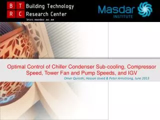
b trc.masdar.ac.ae. Optimal Control of Chiller Condenser Sub-cooling, Compressor Speed, Tower Fan and Pump Speeds, and IGV Omer Qureshi, Hassan Javed & Peter Armstrong, June 2013. Presentation Outline. Introduction SCADA and Heat Balance Analysis Component Models Chiller System Solver

E N D
btrc.masdar.ac.ae • Optimal Control of Chiller Condenser Sub-cooling, Compressor Speed, Tower Fan and Pump Speeds, and IGV • Omer Qureshi, Hassan Javed & Peter Armstrong, June 2013
Presentation Outline • Introduction • SCADA and Heat Balance Analysis • Component Models • Chiller System Solver • Optimization • Conclusion and Future Work
Introduction • Plant under consideration-(4x2500T). • Collection and analysis SCADA • Development of sub models for Individual chiller components • Validation of model • Development of solver- to execute these sub models and predict chiller performance. • Optimize the model to produce set of conditions for optimum power consumption.
District Cooling Plant • Selected District cool Plant • Capacity (4x2500T) • Shell and tube Evaporator and Condenser • Constant speed single stage centrifugal compressor • Capacity control by Pre-rotation vanes • Surge control Variable geometry diffuser • 2-cell cooling tower each with variable speed fan (Fan diameter: 8m) • Variable speed chilled water pump • Constant speed condenser water pump
Chiller Unit 1. Maintenance manual of York Chiller(Source: Tabreed)
Components Models—Chiller Unit • Steady-state models based on first principle • Inputs • Component engineering parameters • SCADA Data • Simple models, less computation time • Four Component models for district cooling plant • Evaporator Model----Shell and tube • Condenser Model----Shell and tube • Centrifugal Compressor Model (Isentropic work + loss Mechanism) • Constant speed • Variable speed • Variable speed pump model
Evaporator Model Assumptions: • No pressure drop considered for refrigerant side • Thermal resistance from refrigerant side is neglected.
Evaporator Model • Two regions for refrigerant were modeled: • Evaporation • Superheating • 𝞮 – NTU Method • Single Stream HX for evaporation • Crossflow HX for super heating Evaporator 1st Pass 2nd Pass
Evaporator Model • Equations utilized in Evaporator Model
Evaporator Model • Equations utilized in Evaporator Model Equation for regressed length: Equation for temperatures:
Evaporator Model 1. Maintenance manual of York Chiller(Source: Tabreed)
Condenser Model Assumptions: • No pressure drop considered for refrigerant side • Thermal resistance from refrigerant side is neglected.
Condenser Model Condenser 1st Pass 2nd Pass • Three regions for refrigerant were modeled: • Sub-cooling • Condensation • De-Superheating • 𝞮 – NTU Method
Condenser Model • Equations utilized in Condenser Model 1a. Sub-Cooling Section(First Pass):
Condenser Model 1b. Condensation Section (First Pass): Mixing Section:
Condenser Model 2a. Condensation Section (Second Pass): 2b. De-superheating Section (Second Pass):
Compressor Model • Integral and mathematically most complex part of chiller • Constant and variable speed compressor model • Non-Dimensional loss model based on Aungier(2000)
Compressor Model-Inputs and Outputs • Constant Speed Model • Variable speed Model
Variable Speed Compressor Model Loss Model Calculations
Variable Speed Compressor Model-Benefits/comparison • Variable Speed Compressor (KW) • Measured Compressor Power (KW) • Compressor Power (KW) • Operation Conditions: • mr(kg/s) • Pout/Pin • No. of Observations
Cooling Tower Model • Effectiveness NTU Method
Cooling Tower Model • Assumptions, Specifications and Input/ Output Variables
Pump Model Mainly there are two mode of operation for these pumps: • Constant flow pump • Variable flow pump with a variable speed drive To model a variable pump power following relationship is used: Where, PMP = pump motor power at rated condition, kW C1, C2, C3 and C4 are pump performance coefficients Also, PLRi = pump part load ratio defined as follows:
Pump Model • Validation Graph • + 5%Error Line
Solver Description Qt,e Tw,in,e Tw,in,c Ve Vc dTsh,e
Optimization • Optimization performed with two configurations: • Chiller Water Flow Optimization • Chiller Water Flow And Condenser Water Flow Optimization • Objective Function: Minimize total power consumption i.e. compressor power and pump(s) power combined.
Optimization • Chiller Water Flow Optimization:
Optimization • Chiller Water Flow And Condenser Water Flow Optimization: Qe = 10,000 kW Ve,opt = 0.349 m3/s Vc,opt = 0.408 m3/s Total Power (KW) Vc (m3/s) Vc (m3/s) Tw,in,e = 14 C; Tw,in,c = 25 C
Optimization • Chiller Water Flow And Condenser Water Flow Optimization: Qe = 8,000 kW Ve,opt= 0.296 m3/s Vc,opt= 0.355 m3/s Total Power (KW) Vc (m3/s) Vc (m3/s) Tw,in,e = 14 C; Tw,in,c = 25 C
Optimization • Chiller Water Flow And Condenser Water Flow Optimization: Qe = 6,000 kW Ve,opt = 0.249 m3/s Vc,opt = 0.332 m3/s Total Power (KW) Vc (m3/s) Vc (m3/s) Tw,in,e = 14 C; Tw,in,c = 25 C
Optimization • Chiller Water Flow And Condenser Water Flow Optimization: Qe= 4,000 kW Ve,opt = 0.205 m3/s Vc,opt = 0.251 m3/s Total Power (KW) Vc (m3/s) Vc (m3/s) Tw,in,e = 14 C; Tw,in,c = 25 C
Optimization • Chiller Water Flow And Condenser Water Flow Optimization: Tw,in,e = 14 C; Tw,in,c = 25 C
Optimization • Chiller Water Flow And Condenser Water Flow Optimization:
Conclusions • Variable Speed compressor provide savings of 30-40% • Variable speed pump for water circulation play an imperative role in reducing overall power consumption of chiller plant. • Modeling of chiller components can be performed with limited engineering information from manufactures.
Future Work • More rigorous compressor loss model • Transient model for the condenser and evaporator • Cooling tower Model • Variable Speed condenser pump • Investigate the effect of pressure drop and resistance from refrigerant side
Q&A 45