Download

1 / 13
130 likes | 228 Views
This project aims to address the water scarcity issue in El Socorro by building a new water distribution system to provide daily access to clean water for the entire community. The plan involves pumping water from a local spring to a storage tank for efficient distribution. Different components like the spring box, delivery pipeline, distribution network, pump, and storage tank are crucial for successful implementation. The project has made progress with site visits, design plans, identification of filtration technologies, and fundraising. Further steps include project implementation, construction, and utilizing the CGI-U platform. Key personnel and submission details are outlined for successful project completion.

E N D
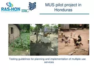
Background Background of Problem: • Every community member’s house in El Socorro is connected to the town’s water distribution system. The system was built a long time ago for a much smaller community. Currently half the population of El Socorro has regular access to the drinking water from home. These residents get water every day in the summer and every other day in the winter due to an insufficient supply of water from the source they are currently using. The other half of the town only gets access from their home system every 15 days in the summer and every three months in the winter. Currently these residents are buying water from the nearest town, Siguatepeque, which is very expensive and a real burden on the community. Consequently all community members want an improved system to distribute and pump water to all community residents. Proposed Plan: • The proposed program is to build a new distribution system solely for the use of the population that does not get regular access. This will then free up the water supply for the other half of the community to get water on a daily basis. Water supply and distribution are the sole needs for El Socorro and is necessary to fulfill basic water demand for 100% of the population. The water system will pump from a local spring to a tank that will distribute water to the population that currently does not have regular access to water.
What’s Been Done What Needs to Happen • Site visit in March 2009 • Basic design plans • Filtration technologies identified • Fundraising begun • Completed Design • Project implementation prepared • Construction • CGI U
Spring Box • This is a container that protects the spring water and collects water to be pumped to the storage tank. It must be sized to have the volume sufficient for a pre-determined water demand. • Springbox Calculator • Additional Information
Delivery pipeline to village • This pipeline conveys water from the spring box to the storage tank. In designing the pipeline, the pipe material and pipe size (diameter) must be selected. Pipe material is selected based on pressure in the pipe. For high pressure (near the pump), HG (galvanized steel) would be used. For lower pressures, PVC pipe is used. Pipe diameter is selected based on velocities and friction losses. The smaller the pipe, the higher the velocity and the higher the friction losses.
Distribution network through village • The distribution network is a network of pipes that convey water from the storage tank to the pilas (taps) where individuals can access water. The design of the distribution network involves selecting a pipe diameter in order to reduce friction losses and maintain sufficient velocity for a known water flow. The goal is to maintain enough pressure in the network so water from the storage tank can reach the pilas. • The design of the entire pipeline (delivery and distribution) and storage tank location requires proper use of the spreadsheet. • Detailing pipeline will require locating points to include flush out valves (Flush 1, Flush 2), air release valves (at high points in delivery line), non-return valves, etc.
Pump • This pump provides energy to the water in order for it to go from the spring box, through the delivery pipeline and reach the storage tank. Pumps are chosen based on pump curves: In general, a pump can provide a certain amount of pressure (head) for a given flow rate. As the flow rate increases, the pump will provide a smaller amount of head. The flow rate is a known value. The amount of head required is based on the location of the storage tank (elevation) and the friction losses through the delivery pipeline. • Sample Pump
Storage tank • The storage tank is the destination of water coming from the delivery pipeline. The storage tank serves two main purposes. First, the location of the storage tank (elevation) provides the pressure to the distribution network of pipes. When the storage tank location is changed, both the delivery pipeline and distribution network must be altered accordingly. Secondly, the storage tank acts as a buffer zone for the water flow. At night, when nobody is using the water, the storage tank fills up. As water demand peaks during the day, this volume of water supplements the flow coming from the source (spring). Hence, the storage tank shall be sized to account for differences in water supply and demand throughout the day.
CGI-U • Team of 4 people • Submission Deadline is Feb 22nd • PDF version of email must be sent to Caitlin Augustin, Ali Habashi, and Richard Walker