Download
1 / 23
230 likes | 238 Views
This paper discusses the problem of flow maldistribution in parallel heat exchangers and explores control alternatives to achieve equal flows in the branches. The study includes simulations, analysis, and conclusions for future work.

E N D
Control of maldistribution of flow in parallell heat exchangers Magnus G. Jacobsen, Sigurd Skogestad Nordic Process Controi workshop, Porsgrunn 29.-30. jan 2009
Outline • Motivation • Problem description • Model description • Simulations • Analysis • Conclusions and future work Nordic Process Controi workshop, Porsgrunn 29.-30. jan 2009
Motivation • The problem is observed in the LNG plant at Melkøya and is probably one of the reasons for suboptimal operation • At the same time, it is an interesting control challenge; • Can we control the system so we have equal flows in the two branches, using only one input? • Obviously, we can achieve this for flows outside the instability area, but by design, we are close to or inside this area. Nordic Process Controi workshop, Porsgrunn 29.-30. jan 2009
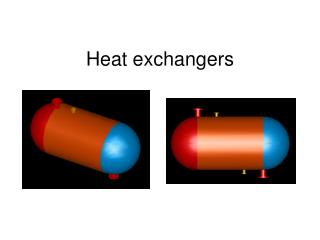
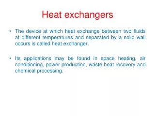
Problem description • When having a vaporizing fluid distributed between two or more parallels, we can have different flow rates in each parallell • This leads to temperature gradients inside the exchanger. This causes increased wear on heat exchanger material, and disturbance on operation of surrounding units. • We may also get liquid in one of the exit streams, this may damage compressors Nordic Process Controi workshop, Porsgrunn 29.-30. jan 2009
Simple model • Heat is transferred from a source of constant temperature and aritmethic mean ΔT is used • Gas phase is assumed ideal and heat capacities are assumed constant • Hydrostatic contribution to pressure drop is neglected • Flow = √(ρΔP/k) where k is a constant • Data used are for water Nordic Process Controi workshop, Porsgrunn 29.-30. jan 2009
Simulations • With one parallell, to establish how overall pressure drop, temperature and density change with increasing flow. • Model is run to steady state for different values of inflow • Next plots show: • Pressure drop as function of molar inflow • Outlet temperature as function of molar inflow • Outlet density as function of molar inflow Nordic Process Controi workshop, Porsgrunn 29.-30. jan 2009
Dynamic simulation with two parallell tanks • Individual flows may vary, but total is constant • Total flow divided by 2 lies inside instable region • Inlet pressures are equal • Adds inlet pressure as algebraic variable (DAE system) • Plots show: • Inflows • Outlet vapour fractions • Temperatures • Inlet pressure (common for both tanks) Nordic Process Controi workshop, Porsgrunn 29.-30. jan 2009
Linear analysis • Linearization (using Simulink) of the model after 30 seconds shows that the initial operating conditions are unstable • Linearization after 300 seconds shows that the final operating conditions are stable • This indicates that if the hot side temperature is not changing, the system will stabilize at the operating point where maldistribution is present Nordic Process Controi workshop, Porsgrunn 29.-30. jan 2009
Controllability • We have considered the following measured variables: Overall pressure drop (dP), difference in internal pressure (ΔP) , difference in outlet temperature (ΔT ) • Total feed rate nin is the manipulated variable • At the instable operating point, dP is the only measurement out of those considered which changes with total flow (the others are zero) Nordic Process Controi workshop, Porsgrunn 29.-30. jan 2009
At both operating points, the linearized system is state controllable, that is, the controllability matrix has full rank • However, because of the fast transition from the unstable to the stable region, control might be difficult • For example, the transfer function from total flow to overall pressure drop has a duplicate real RHP zero at almost the same location as its RHP pole. • At the instable solution, this is the variable that is simplest to measure. Nordic Process Controi workshop, Porsgrunn 29.-30. jan 2009
Control alternatives • Control inside the instable area is difficult anyway • Multivariable control – will it be fast enough? • Split-range SISO control? • Inside instable area, use feedback to control pressure difference • When ΔT is nonzero, reduce total flowrate temporarily • But can we then go back to nominal operating conditions without going unstable? Nordic Process Controi workshop, Porsgrunn 29.-30. jan 2009
Remember: Nordic Process Controi workshop, Porsgrunn 29.-30. jan 2009
Conclusions and further work • Control inside the unstable area is difficult (but probably possible) • For the LNG plant it may be easier because of slower dynamics • Next step will be trying out different control strategies Nordic Process Controi workshop, Porsgrunn 29.-30. jan 2009