Download
1 / 46
1.15k likes | 2.69k Views
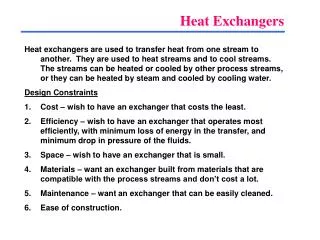
Heat exchangers. The device at which heat exchange between two fluids at different temperatures and separated by a solid wall occurs is called heat exchanger. Its applications may be found in space heating, air conditioning, power production, waste heat recovery and chemical processing.

E N D
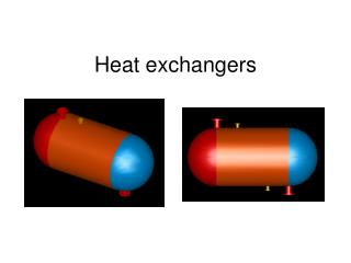
Heat exchangers • The device at which heat exchange between two fluids at different temperatures and separated by a solid wall occurs is called heat exchanger. • Its applications may be found in space heating, air conditioning, power production, waste heat recovery and chemical processing.
The principle Types of heat exchangers • Double pipe heat exchangers • Shell and tube heat exchangers • Plate and frame heat exchangers • plate fin heat exchangers • Air cooled heat exchangers • Spiral heat exchangers • Fired heaters [boilers]
1-Double pipe heat exchanger Construction
1-Double pipe heat exchanger Hairpin unit
Flow patterns 1-Co current flow [parallel flow]
3-Cross flow Intermediate effectiveness between parallel flow and couterflow exchangers. [not used with double pipe]
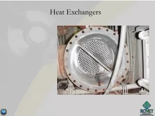
2-Shell and tube heat exchanger • The most common used type….why? • The configuration gives a large surface area in a small volume (i.e. compact) • Can be constructed from a wide range of materials • Well established design procedure
2-Shell and tube heat exchanger • Types of shell and tube heat exchangers: • Fixed tube sheet (plate) • U- tube • Internal floating head without clamp ring • Internal floating head with clamp ring • External floating head • Kettle re-boiler with U- tube bundle
Fixed tube sheet (plate) H.X • Main components
Shell types[ passes] Shell side flow arrangements are generally one of the following illustrated F E Two shell pass One shell pass G H Longitudinal baffles Split flow Double split flow J X Divided flow Cross flow
Example Split flow type
Factors affecting the choice of the shell arrangements • The amount of cooling and heating required • The pressure drop • The type of service [for instance the shell arrangement that provides space for vapors to accumulate is the kettle type re-boiler
Baffles • Why are baffles used? • To support the tube • To direct the fluid stream across the tube • To improve the rate of heat transfer Shell Tubes Baffle
When to use this type? • It is used where the temperature difference between the shell side and tube side fluids is quite great….WHY? • Because the tubes are free to expand since the tube bundle is fastened to only one tube sheet.
Allocation of fluids Tube side • Put dirty stream on the tube side [fouling fluid] - easier to clean inside the tubes • Put high pressure stream in the tubes to avoid thick, expensive shell • When special materials required for one stream, put that one in the tubes to avoid expensive shell • Put corrosive fluid in the tube tom reduce the cost of expensive shell • Put toxic fluid in the tube to minimize leakage
Shell-Side • 1. Viscous fluid to increase (generally) the value of "U“ [Cross flow gives higher coefficients than in plane tubes, hence put fluid with lowest coefficient on the shell side] • 2. Fluid having the lowest flow rate • 3. Condensing or boiling fluid Note If no obvious benefit, try streams both ways and see which gives best design
Heat exchangers problems • Exchanger fouling • Corrosion • vibration
Definition of fouling • Build up of various kinds of deposits on the parts of an exchanger • Types of fouling • Salt deposit [as Ca and Mg deposits in case of hard water] • Chemical fouling [as corrosion products] • Biological fouling [as growth of algae which form insulating layer] • Coking
Effect of fouling on the H.X performance • Increase the thermal resistance and reduce the rate of heat transfer [decrease the efficiency of the H.X] • Increase the surface roughness [the flow of the fluid is restricted] and increase the pressure drop • Troubles that indicate the presence of fouling • Change in temperature or pressure • Change in flowrate [outlet flow rate]
Factors affecting the kind and degree of fouling • The materials used in the heat exchanger • Some materials corrode faster than others providing corrosion products which decrease heat transfer • Rough surface provides cavities for the build up of deposits • Fluid velocity • Affect the fouling rate [as the velocity increase the fouling rate decrease]
How to handle the problem of fouling • Antifoulants prevent the formation of deposits • Inhibitors [as corrosion inhibitors] prevent chemical reactions which might cause deposits to build up • Frequent cleaning of the H.X [maintenance]
Corrosion of heat exchangers • Another series problem in heat exchangers is corrosion • Severe corrosion can and does occur in tubing and very often with • common fluids such as water • To avoid corrosion • Proper material selection based on full analysis of the operating fluids, velocities and temperatures is a must • Heavier gauge tubing is specified to offset the effect of corrosion followed by proper start up operating and shut down procedure • Protection of the heat exchanger from corrosion [e.g.cathodic protection] • Treatment of the cooling water used and using inhibitors
Heat exchangers vibration • Vibration of the tubes as a result of the flow of the shell side past them is important phenomena specially when the H.X size and flow quantities of flow are increased • Vibration effects • Vibration has a bad effecton both tubes and shell • The joints between the tubes and tube sheet can fail due to vibration causing leakage • It causes leakage in the joints between shell and tubes • Increase the shut down time to repair the H.X
Factors affecting tube vibration • Tubes geometry [layout] • Material of construction • Means of support • Heat exchanger size • Flow quantities
How to avoid vibration • Using inlet support baffles • Using double segmental baffles [improve tube support] • Using j shell type [ divided flow type to reduce the shell velocity] Inlet support baffles Double-segmental baffles
Air cooled heat exchanger • Used for cooling and condensation and used when cooling water is in short supply or expensive • They can also be competitive with water cooled units even when water is plentiful • Most common used in petroleum and gas processing industries • Main components • Air cooled exchangers consist of banks of finned tubes over which air is blown or drawn by fans mounted below or above the tube • If the fan is mounted below the tubes the unit is termed forced draft unit and if the fan is mounted above the tubes the unit is termed induced daft
Air cooled heat exchanger Forced draft air cooled heat exchanger [cross flow]