Download
1 / 30
390 likes | 841 Views
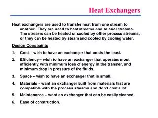
Heat Exchangers. Chapter 18 ChEN 4253 Terry A. Ring. Flow Patterns. Parallel Flow Counter Current Flow Shell and Tube with baffles Cross Flow. Temperature Profiles. ΔT = Approach Temperature. Heat Exchanger Temperature Profiles. Flow Structure. Q=U A F ΔT lm-counter.

E N D
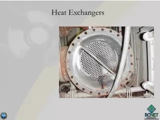
Heat Exchangers Chapter 18 ChEN 4253 Terry A. Ring
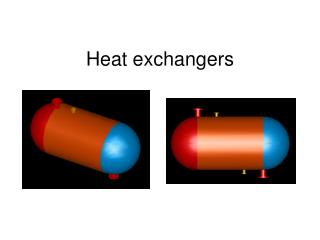
Flow Patterns • Parallel Flow • Counter Current Flow • Shell and Tube with baffles • Cross Flow
Temperature Profiles ΔT = Approach Temperature
Flow Structure Q=U A FΔTlm-counter
Overall Heat Transfer Coefficient • Series of Resistances • Basis • Inside • Outside Inside Tubes Rf=fouling factors, inside and outside See table 18.5 for range of U values for different cases.
Heat Transfer inside a tube Also other correlations valid over wider ranges
Heat Transfer outside of Tube Also other correlations valid over wider ranges
What Temperature Approach • Heuristic 26. • Near-optimal minimum temperature approaches in heat exchangers depend on the temperature level as follows: • 10°F or less for temperatures below ambient, • 20°F for temperatures at or above ambient up to 300°F, • 50°F for high temperatures, • 250 to 350°F in a furnace for flue gas temperature above inlet process fluid temperature.
Where are the Heat Exchangers? What is happening in each Octane Reaction 2C2H4 + C4H10 C8H18 P= 20 psia, T=93C, X=98% Conversion TBP C2H4 −103.7 °C C4H10 +0.5 °C C8H18 +125.52 °C
Heat Transfer With Phase Change • Tricky Problems • Examples • Reboiler on Distillation Unit • Condenser on Distillation Unit • Flash Units • Boilers
A Word About Steam • Simulator Assumptions • Inlet – Saturated Vapor • Pressure • 100% Vapor • Outlet – Saturated Liquid • Liquid Only Leaves via steam trap • Pressure = Pin- ΔP (1.5 psi, Heuristic-31) • 100% Liquid
Where are the Tricky Heat Exchangers?
Condensation Heat Transfer Assume Film Condensation • Drop Wise Condensation • Special Case • Very High Heat Transfer • 5 to 10 x Film Condensation • Film Condensation • Laminar
Boiling Heat Transfer Coefficient Highest Heat Transfer Coef. But hard to control HX operating here Various correlations depending upon boiling mechanism
Heuristic 28 • Boil a pure liquid or close-boiling liquid mixture in a separate heat exchanger, using a maximum overall temperature driving force of 45 F to ensure nucleate boiling and avoid undesirable (low h) film boiling.
Aspen - Zone AnalysisProMax – Heat Release Increments • Heuristic 29. • When cooling and condensing a stream in a heat exchanger, a zone analysis, described in Section 18.1, should be made to make sure that the temperature difference between the hot stream and the cold stream is equal to or greater than the minimum approach temperature at all locations in the heat exchanger. The zone analysis is performed by dividing the heat exchanger into a number of segments and applying an energy balance to each segment to determine corresponding stream inlet and outlet temperatures for the segment, taking into account any phase change. A process simulation program conveniently accomplishes the zone analysis.
Pressure Drop & Flow Rate • Laminar vs. Turbulent • Heuristic 31. • Estimate heat-exchanger pressure drops as follows: • 1.5 psi for boiling and condensing, • 3 psi for a gas, • 5 psi for a low-viscosity liquid, • 7-9 psi for a high-viscosity liquid, • 20 psi for a process fluid passing through a furnace.
Controlling ΔP in Simulator • Shell side • Nozzle diameter • Inlet and Outlet • Number of Baffles • Tubes • Number, diameter, pitch, No. passes • Tube side • Nozzle diameter • Inlet and Outlet • Tubes • Number, diameter, pitch, No. passes Note interactions!
Shell Heads, Shell Type • See ProMax Help/index “Shell, types”
HX Cost • Size Factor HX Area • CBase(6-2000)=exp[11.0545-0.9228*ln(A)+0.09861*ln(A)2] • Purchase Price • CP-fob=FP(P)*FMaterial(A)*FL(L)*CBase*(CPI/394) • CBM=FBM*CP-fob • CBM=3.17*CP-fob • Cost depends on HX Area • Pumping Cost • Work = Q*ΔP
Controlling A in Simulator • A = Ntubesπ Dtubes Ltubes • Shell • Shell Diameter and pitch determines Ntubes • Tubes • Dtubes • Ltubes • Tube pitch-The transverse pitch is the shortest distance from the center lines of two adjacent tubes. • Tube pitch ratio 1.25 to 1.5 typically
Controlling U in a Simulator • For a given heat duty and geometry - U determines the HX area • Steps • Identify the controlling heat transfer resistance • ho-Manipulate the shell side Reynolds number • Shell diameter • Tube pitch • Number of baffles • hi-Manipulate the tube side Reynolds number • Tube diameter • Number of tubes (shell diameter and tube pitch) • Number of passes • If odd things happen check to see that you have the same controlling heat transfer resistance Note interactions!
Other Issues • Materials of Construction • Strength at temperature, life time, heat conduction, fouling • Design layout • Tube pitch, baffles, tube and shell diameters
Heat Exchanger Problems • Temperatures Cross Each Other • Non-functioning Exchanger • To solve increase approach ΔT • Condensation/Evaporation • Heat transfer with multiple heat transfer coefficients in a single apparatus • Various regimes of boiling • Various regimes of condensation Zone Analysis