Download
1 / 26
260 likes | 270 Views
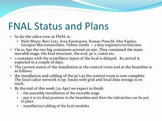
SRF Plans at ANL & FNAL. Bob Kephart ILC Program Director, Fermilab ANL-FNAL-U of C Collaboration Meeting Oct 12, 2009. Superconducting Radio Frequency. ILC = International Linear Collider, 500 GeV e+e- collider Project X = New multi-MW proton source at Fermilab.

E N D
SRF Plans at ANL & FNAL Bob Kephart ILC Program Director, Fermilab ANL-FNAL-U of C Collaboration Meeting Oct 12, 2009
Superconducting Radio Frequency ILC = International Linear Collider, 500 GeV e+e- collider Project X = New multi-MW proton source at Fermilab • Superconducting Radio Frequency is an “enabling” technology relevant for any of a number future accelerators at FNAL and ANL • Both institutions have near-term and long-term aspirations to build/upgrade SRF based accelerators • FNAL: Project X, ILC, Muon Collider • ANL: ATLAS upgrades, ILC, future SRF based light sources • ANL SRF group: long & distinguished history (ATLAS) • FNAL is new at SRF: but effort has grown rapidly natural for us to collaborate • Both institutions are expanding SRF infrastructure May 18-19, 2009 2
ANL-FNAL collaboration on SRF History: 2005: choice of SRF technology for the ILC Gave a strong impetus to ongoing ANL-FNAL SRF collaboration as part of the TESLA Collaboration (3.9 GHz cavity processing at ANL) 2006-8 EPP2010 and HEPAP strong endorsement of ILC R&D Emphasis by the Global Design Effort on cavity gradient & yield Realization: U.S. must master ILC SRF technology (developed @ DESY) Fermilab also had a growing interest in Proton Driver Project X Intense proton source for long baseline neutrinos Joint design effort with ANL (Peter Ostrumov) Px uses ILC cavities, gradient lower but yield important Also uses spoke resonators developed at ANL Development of an ANL/FNAL cavity processing facility at ANL Development of complementary SRF infrastructure at FNAL 2009-present Lots of progress, commissioning infrastructure!
ILC R&D Mission & Goals Mission (both ANL and FNAL): Work with the GDE Americas Regional Team (ART) to develop the ILC design & gain approval of the project Goals: Participate in the Technical Design Phase (now 2012) Participate in Accelerator Physics, Conventional Facilities Design, and global systems work to further the ILC design Work towards GDE SRF goals S0: Cavity gradient of 35 MV/m; good yield S1: Cryomodules with average gradient > 31.5 MV/m S2: One or more ILC RF unit with ILC beam parameters Perform R&D and value engineering to reduce costs Become a trusted international partner SRF !
Project X R&D Plan Goals: Pick configuration in Early 2010 Complete baseline design, cost and schedule estimates in 2012 Technical component and infrastructure development Linac (325 MHz) High speed variable chopping patterns (325 MHz) SRF spoke resonator development RF control of multiple SRF cavities from single klystron Linac (1.3 GHz) SRF Cavity & CM development coordinated with ILC 25 MV/m gradient with good yield ICD-1: (20 mA average) x 1.25 msec x 2.5 Hz 3 times the charge/pulse of ILC ICD-2: ILC cryomodules operated with CW 2-8 GeV linac requires 20 ms 1 ma pulses H- transport, multi-turn injection, space charge, e-cloud, civil, etc SRF !
1.3 GHz Joint Development Strategy Project X shares 1.3 GHz technology with the ILC Project X requires 20-52 ILC-like cryomodules. In detail they will not be identical to ILC: Gradient: 25 MV/m (but try for higher) Yield is important for the cost Close coordination of Project X & ILC R&D Developing U.S. cavity vendors Cavity gradient and yield! U.S. results mostly from JLAB New ANL-FNAL infrastructure will double U.S. process and testing Px 4 year construction 1 CM/month Building extensive infrastructure at FNAL, JLAB, ANL, etc for both Project X and ILC R&D Px ILC U.S.
ILC R&D (Px) elliptical cavity processing Cavity Fabrication By Industry Plan in Place since 2006 Surface Processing @ Cornell Surface Processing @ ANL/FNAL Surface Processing @ Jlab ~10/yr ~50/yr ~50/yr Vertical Testing @ Jlab Vertical Testing @ Cornell Vertical Testing @ FNAL Exists Cavity Dressing & Horizontal Testing @ Fermilab Developing
ILC: Cavity processing at Argonne • Joint facility built by ANL/FNAL collaboration • 2000 ft2 facility @ ANL complete Mar 2009 • Commissioning, excellent single cell results • EP processing of 9-cells has started • Together with JLab are the best cavity processing facilities in the US for ILC or Project X Ultrasonic Cleaning Electropolishing High-pressure rinse
Chemistry room and new test cryostat New test cryostat at ANL 9-cell Electropolishing
ILC: 2 Kelvin Testing for ILC and other SRF Cavities • New large test cryostat system (TC3) is being commissioned at ANL • Useful for testing a broad range of ILC and Project X cavities
New FNAL SRF infrastructure 1st Dressed Cavity Cavity tuning machine VTS HTS VTS String Assembly MP9 Clean Room Final Assembly 1st U.S. built ILC/PX Cryomodule
HINS 325 MHz Single Spoke Design Parameters SSR1-02, the 2nd SSR1 prototype. Fabricated by Roark. Original Plan * Eacc is the total accelerating voltage divided by Leff, where Leff = (2/3) = 135 mm, the distance between the edges of the accelerating gaps at the two endwalls.
HINS: A pair of FNAL single spoke cavities processed at ANL • Chemical polishing, high-pressure rinsing in G150 by Argonne and Fermilab SRF staff • Cold testing performed at Fermilab • Both cavities have achieved world leading performance
Spoke Resonator VTS of bare cavity 1.E+11 Q @ 2K Q @ 4K after 2K run Radiation @ 2K Radiation @ 4K after 2K run Jump thru MP barrier from 24 to 33MV/m 1.E+10 1.E+01 MP from ~11 MV/M 1.E+09 1.E+00 Q0 Radiation (mR/hr) 1.E+08 1.E - 01 1.E+07 1.E - 02 0 5 10 15 20 25 30 35 E (MV/m) acc Project X Operating Point 15 MV/M @2 K Q0 .vs. Eacc and x-ray intensity as measured at the top of the VTS
New RF Unit Test Facility at Fermilab An important facility for both Project X & ILC R&D 1st Cryomodule moving to NML
Progress at NML CM Feed Can Large Vacuum Pump 1st Cryomodule Test fit He Refrigerator Control Room Capture Cavity II @ NML
Broad collaborative SRF materials R&D Program • Collaboration of ANL,FNAL,U of C materials scientists! • See Prolier, Sibener, Cooley talks • Example • Cavities often limited by defects near EB weld • Pits observed in samples after EP. Why? • Diagnostic tools ! Pits appear after EP !
SRF: New Temperature Mapping New single-cell temperature mapping system uses multiplexed diodes as sensing elements New diode based system with 960 sensors and 62 wires can be installed in about 15 minutes Traditional carbon resistor based system
SRF: Optical Inspection System • KEK/Kyoto inspection system delivered, installed, commissioned early in 2009 • Expert assistance to optimize system in March 2009 • In routine use; software development underway Accel7 on the optical inspection stand Optical inspection optimization
SRF: Laser Melting of Nb Surface • Preliminary experiments show a pit cannot be removed by BCP or EP, even after ~150 um removal • Fermilab is investigating: Laser Melting 100 µm 14 µm
Summary Strong collaborative partnership on SRF has grown between ANL, Fermilab, and U of Chicago Extensive SRF infrastructure being built at both ANL and FNAL Starting to make significant impact on projects ILC, Project X, etc (Results at SRF09 in Berlin) Collaboration in SRF materials & surface science Many complementary skills and facilities A success story! A good collaboration ? Yes! The whole is greater than the sum of the parts
Project X: What is it? A new multi-MW Proton Source under development at Fermilab. Enables a world-class Long Baseline Neutrino Experiment (LBNE) via a new beam line pointed to DUSEL in Lead, South Dakota. Enables a broad suite of rare decay experiments Currently two versions of this machine are under consideration. Both versions provide 2 MW of beam power to LBNE ICD-1 is based on a pulsed 8 GeV 20 ma ILC-like H- SRF linac ICD-2 employs a 2 GeV 1 ma CW SRF linac that accelerates H- or P’s Provides an additional 2 MW to the high intensity program Very flexible beam manipulation via RF separators 2-8 GeV = either a pulsed linac or a rapid cycling synchrotron. Project X website: http://projectx.fnal.gov/
ICD-1 SRF Linac Technology Most ~ 7/8 of LINAC is built of ILC-like CM but ~ 25MV/M gradient