Download
1 / 19
190 likes | 197 Views
This presentation discusses the characterization and tuning features of the electro-optical transceivers used in the KM3NeT optical network, including wavelength tuning and device aging. Preliminary results and future testing plans are presented.

E N D
Characterization of the electro-optical transceivers in the KM3NeT optical network S.Pulvirenti, F. Ameli, A. D’Amico, G. Kieft, J-W Schmelling for KM3NeT Collaboration 15-09-2015
Summary • Introduction • The electro-optical transceiver in KM3NeT • OESolution SFP Transceiver • Wavelength tuning • (First) Tests atNikhef • Device aging and wavelengthdrift • Test bench • Test Procedure • Preliminary results • Conclusion and future Test
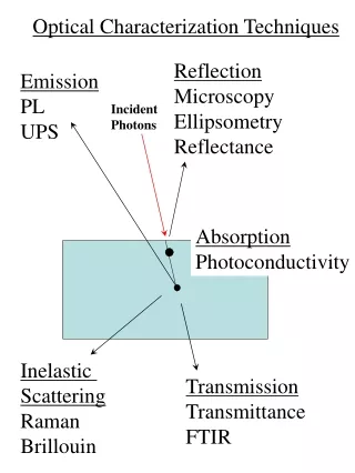
Introduction The presentation shows preliminary results about the characterization of the tuneable features of the electro-optical transceivers used in KM3NeT network. Over the telescope life time, precise temperature control of the laser is required to maintain stability of the central frequency, complying with the ITU-T G.694.1 recommendations of the International Telecommunication Union. This characterization is required to compensate for the expected wavelength drift due to aging factors.
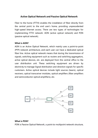
SFP Transceivers in KM3NeT They are a key element in the KM3NeT network, present in DOM, JB, Tower Floor, Shore Station
OESolution SFP Transceivers The data transport over the KM3NeT optical network is based on the Dense Wavelength Division Multiplexing (DWDM) technique with optical channels spaced 50 GHz apart, a bit rate of 1.25Gbps and up to 100 km span length. • The digital diagnostic monitoring interface allows real time access to the device operating parameters: • Transmitted Optical Power • Received Optical Power • Transmitter Bias Current • Transceiver Temperature • Laser Temperature • Supply Voltage • TEC Current KM3NeT SFP Requirements
Wavelength tuning The wavelength tuning feature of a SFP is a special feature which is not required by the DWDM SFP MSA standards. The principle of the wavelength tuning is based on changing the temperature of the TOSA (Transmission Optical SubAssembly). To be more precise change the temperature of the laser cavity. Inside a SFP there is a temperature control circuitry which on its turn is connected to a microcontroller. The actual change of temperature is done via a TEC (Thermoelectric cooling) controller. This TEC controller on its turn is connected to the microcontroller where it gets its set-point from. The actual wavelength tuning by the user is done by changing data in the microcontroller memory which is translated to the temperature setting of the TEC and thus the TOSA temperature. All the communication is done via the I2C bus of the SFP transceiver. The expected wavelength change is typically 100 pm/°C
(First) Tests at Nikhef • Wavelength measurements at NikhefperformedusinganAndowavelength meter, model modelAQ6140,instead of an OSA. • Mainspecifications: • Wavelength range 1270 to 1650 nm • Wavelength accuracy±2 ppm (1550 nm, 1310 nm: ±0.003 nm) • Minimum resolvable seperation 10 GHz or less (1550 nm: 80 pm, equal power line input)
Device aging and wavelength drift Long-term device reliability is characterized by the increase in threshold current and the decrease in optical output power. The aging of the laser is associated with loss of optical efficiency resulting in a drop of the emitted optical power. In the application it is preferred to operate the device in constant output power mode. As the device undergoes aging the dissipated power increases resulting in a rise in the junction temperature. The lasing wavelength is a sensitive function of the junction temperature. The lasing wavelength of a DFB laser diode is given by the simple equation: where is the n effective refractive index and is the grating pitch. In order to obtain a desired wavelength accurately, both parameters have to be well controlled. Moreover, the effective refractive index can change with the driving conditions such as laser temperature or laser current. Due to the above reasons, temperature control is often used to fine-tune the DFB wavelength precisely to an ITU-T grid. Over the device lifetime, the laser diode will exhibit wavelength drift. Eventually the wavelength drift could drive the channel into the neighbouring one then disrupting the communication.
Test Bench FCM Board Optical Spectrum Analyzer Xilinx Spartan6 - FPGA uBlaze I2C SFP Laser RS232 Communicate with Host PC (RS232) • A MicroBlaze microcontroller is embedded in the FCM FPGA: • Soft IP core (synthesizable); • Xilinx development environment; • Peripheral availability for standard communication protocol with drivers and APIs; • A dedicated SW has been written to: • read/write Laser registers (I2C); • implement tuning procedure for OESolutions Laser; • communicate with Host PC (RS232);
Test bench tools • FCM – Floor Control Module is KM3NeT-IT Floor Control Module: • Communication with On-Shore through SFP Laser; • - Use of Custom Protocol • Collection of digital streams from 6 PMTs located in the Optical Modules; • Collection of data from 2 hydrophones; • Communication with floor oceanographic instrument • Management of local sensors (Temperature, Relative Humidity, Currents and Voltages, etc.) • See Carlo Nicolaus’s Talk • OSA – Optical Spectrum Analyzer: • Wavelength range [nm] 1250 to 1650 • Resolution bandwidth FWHM 0.065 nm • Wavelength uncertainty [nm] ± 0.05 • Wavelength repeatability [nm] ± 0.003 • Wavelength linearity [nm] typical ± 0.01
Test Procedure • Warm up time: > 15 minutes • Initial settings of the transceiver: Factory settings • Disable the transceiver alarms • Store the factory tuning value • Temperature scan 2°C • Wavelength scan: • Acquisition of factory settings • Four samples before scan start (at nominal wavelength) • Eight samples during the wavelength scan. • Four samples after scan stop (at nominal wavelength)
Preliminary results (over 8 scan samples) Wavelength vs Laser temperature
Preliminary Results (Linear Fit) Example CH 30C (λ = 1553,33 nm)
Preliminary results – CH 59C λ = 1530,33 nm Factorysettings (4 samplesscan) Factorysettings (4 samplesscan)
Preliminary results – CH 59C Linear fitbetween Laser temperature and Tuning Value
Conclusion and Future Test • Aging stress test – Monitor the SFP behavior in a long period and check the center wavelength stability at high temperature • Accumulate more statistics (more devices of the same wavelength) • Characterize more devices covering the whole C band within • ± 100 pm from the nominal wavelength • Aim to predict the correction to be applied • in case of a drift of more than ± 50 pm