Download
1 / 71
900 likes | 1.7k Views
Optical Core Networks Optical Transport Network. Achille Pattavina, Politecnico di Milano, pattavina@elet.polimi.it Guido Maier, Politecnico di Milano, maier@elet.polimi.it. Outline. Protocol layering Signalling Transport hierarchy. Optical transfer layer.

E N D
Optical Core NetworksOptical Transport Network Achille Pattavina, Politecnico di Milano, pattavina@elet.polimi.it Guido Maier, Politecnico di Milano, maier@elet.polimi.it
Outline • Protocol layering • Signalling • Transport hierarchy Optical transfer layer
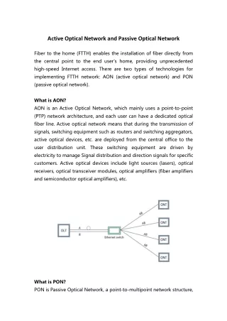
OTN protocol layersFunctions needed to support OTN • The Optical Transport Network (OTN) • The OTN layer is itself a layered set of protocols which perform control and management basic functions regarding • Lightpaths as switched optical-circuit entities • Propagation and maintenance of wavelength optical signals • Fault detection on links and switching equipment • Fault recovery (protection)
OTN protocol layersITU-T G-872: Architecture of OTN • The OTN protocol layer has been standardized by ITU-T • Basic architecture definition: G-872 recommendation (1999 – conclusion of a preliminary work started in 1997 by G-otn study-group) • Physical layer interfaces (parameters and testing points): G-959.1 recommendation • Many other recommendations specifying details have been issued(G-709, G-870 to G-879, G-957, G-652, G-653, G-655, G-692, etc.) • A work in progress: some aspects are still under discussion • Optical Transport Network (OTN) definition • “Optical networks are comprised of functionality providing transport, multiplexing, routing, supervision and survivability of client signals that are processed predominantly in the photonic domain”. • The protocol architecture follows the principles of client-service layering
OTN protocol layersOTN sublayers • The OTN layer-stack is composed of four layers • Optical channel sublayer (OCh) • Optical multiplex section (OMS) • Optical transmission section (OTS) • Physical media layer • Fiber-type specification, developed in other Recommendations Electronic Layers OCh- Optical Channel OMS- Optical Multiplex Section OTN OTS- Optical Transmission Section Physical media (optical fiber)
OTN protocol sublayersSimplified scheme of an OTN connection Tx Rx Electronic layers OCh OMS OTS Physical media DXC Electronic switch OXC Mux Optical switch Demux EDFA
OTN protocol sublayers - OChSimplified scheme of an OTN connection Tx Rx OCh trail Electronic layers OCh OMS OTS Physical media DXC Electronic switch OXC Mux Optical switch Demux EDFA
OTN protocol sublayersOptical channel sublayer • Optical channel layer network: This layer network provides end-to-end networking of optical channels for transparently conveying client information of varying format (e.g. SDH STM-N, cell based ATM, GFP frames, etc.) • To provide end-to-end networking, the following capabilities are included in the layer network • optical channel connection rearrangement for flexible network routing • optical channel overhead processing for ensuring integrity of the optical channel adapted information • optical channel supervisory functions for enabling network level operations and management functions, such as connection provisioning, quality of service parameter exchange and network survivability • Typical involved devices: switching subsystems of OXCs and OADMs • Optical channel entity • The lightpath (or optical circuit) • It transports the digital client between 3R regeneration points
OTN protocol sublayersOptical channel sublayer (II) • Optical channel trail terminations • Validate connectivity integrity • Assess transmission quality (defect detection) • E.g. by BER measurements • Transmit defect indications • Network connection functions • Routing • Adaptation to the client electronic layers • Protection and restoration • Management capabilities • Continuity supervision: loss of continuity detection • Lightpath trace identification • Defect indication • Performance monitoring • Adaptation management: payload type indication
OTN protocol sublayers - OMSSimplified scheme of an OTN connection Tx Rx OMS trail OMS trail OMS trail OCh trail Electronic layers OCh OMS OTS Physical media DXC Electronic switch OXC Mux Optical switch Demux EDFA
OTN protocol sublayersOptical multiplex sectionsublayer • Optical multiplex section layer network: This layer network provides functionality for networking of a multi-wavelength optical signal • Note that a "multi-wavelength" signal includes the case of just one optical channel • The capabilities of this layer network include • optical multiplex section overhead processing for ensuring integrity of the multi-wavelength optical multiplex section adapted information • optical multiplex section supervisory functions for enabling section level operations and management functions, such as multiplex section survivability • These networking capabilities performed for multi-wavelength optical signals provide support for operation and management of optical networks • Typical involved devices: de/multiplexing subsystems of OXCs OADM
OTN protocol sublayersOptical multiplex sectionsublayer (II) • Multiplex section entity • Set of optical channels of specified aggregated bandwidth • Each channel has a defined carrier wavelength • Multiplex section trail terminations • Assess the transmission quality (defect detection) • E.g. by monitoring wavelength values in the WDM signal to detect deviations from the nominal values • Transmit defect indications • Management capabilities • Continuity supervision: loss of continuity detection • Defect indication
OTN protocol sublayers - OTSSimplified scheme of an OTN connection Tx Rx OMS trail OMS trail OMS trail OCh trail Electronic layers OCh OMS OTS trails OTS trail OTS trails OTS Physical media DXC Electronic switch OXC Mux Optical switch Demux EDFA
OTN protocol sublayersOptical transmission sectionsublayer • Optical transmission section layer network: This layer network provides functionality for transmission of optical signals on optical media of various types (e.g. G.652, G.653 and G.655). • The capabilities of this layer network include: • optical transmission section overhead processing for ensuring integrity of the optical transmission section adapted information; • optical transmission section supervisory functions for enabling section level operations and management functions, such as transmission section survivability. • Typical involved devices: optical amplifiers (e.g. EDFA gain-control, etc.), transponders, all-optical regenerators
OTN protocol sublayersOptical transmission sectionsublayer (II) • Transmission section entity • Identical to the optical multiplex section entity (set of wavelength channels): one-to-one mapping between OMS and OTS • OTS also manages the optical supervisory channel (OSC) carrying information both for OTS and OMS • Optical transmission section trail terminations • Validate connectivity • Assess transmission quality (defect detection) • E.g. by monitoring power levels of the WDM channels to drive the equalization systems of optical amplifiers and transponders • Transmit defect indications • Management capabilities • Continuity supervision: loss of continuity detection • Trail trace identification • Defect indication • Performance monitoring • Management communications: message-based channel
OTN protocol sublayersLightpath with regeneration and -conversion OCh trail Rx Tx Tx 2 Rx Tx Tx 1 Rx Rx Rx Tx Tx OA Rx • Transponders of transit nodes should not be OCh trail terminations • Following this rule, the 1 to 1 correspondence between lightpath and OCh-trail is preserved even if the lightpath undergoes regeneration and/or wavelength conversion in middle points • This issue appears still not clear in the recommendations
Outline • Protocol layering • Signalling • Transport hierarchy Optical transfer layer
OTN protocol signalingOverhead (OH) • OMS-OH and OTS-OH are carried onto the OSC (Optical Supervisory Channel), corresponding to one dedicated wavelength channel in the multiplex (prescribed by ITU-T G.872) • OSC is terminated at every node to perform monitoring/control functions in electronic • Optical data channels (wavelength channels) are transferred transparently • OCh-OH transmission under debate for a long time • Two possible implementation technologies proposed: • Associated Channel: one independent supervisory channel for each OCh • Common Channel: a single supervisory channel shared by plenty OChs • Advantages of the associated-channel overhead solution • Direct trail-tracing capability • Scalability • Lowest latency communications between OCh trail terminations (important for protection switching)
OCh-OH transmissionAssociated Channel overhead • An implementations proposed in the past: • Sub-Carrier Modulation (SCM) • Subcarrier modulated signal added to each Overhead sequence Freq. converter Transmitted sequence Data sequence High-frequency modulator Low-frequency modulator Low-pass filter Detector High-pass filter
OCh-OH transmissionAssociated Channel overhead • The actual implementation accepted in the standard: • Digital (or TDM) Wrappers (DW) • Overhead bytes digitally added to the signal Bo = payload bitrate B = transmission bitrate Lp = frame-payload length Lh = overhead-seq. length Overhead sequence Transmitted frame Data sequence (frame payload) TDM multiplexer (digital wrapper) Modulator Detector TDM demultiplexer (digital unwrapper)
Optical channel overhead transmissionAssociated Channel overhead (II) • Pros and cons • Sub-Carrier Modulation (SCM) • (+) Simple detection by filtering • (-) Adds noise Limited OH bit-rate (<<1%) • (-) Frequency SC depend on client signal • (-) Large distances between regenerators imply its elimination ? • Digital (or TDM) Wrappers (DW) • (+) Synchronized with data traffic • (+) OH capacity < 10% • (+) Same signal degradation as the regular WDM payload information • (-) Required OEO (bitrate dependent) • Functions that can be supported • Sub-Carrier Modulation (SCM) • Only OCh trace and identification • Digital (or TDM) Wrappers (DW) • Latency sensitive OAM functions • Forward Error Correction (FEC) Digital wrapper (DW)proposed by Lucent, Itachi and many others; finally selected forstandardization
OTN protocol sublayersOpen issues • Items still under study • Protection control: automatic protection-switching protocol • Connection supervision • Signal quality supervision and performance monitoring in OMS • Signaling format on the OSC • …
Outline • Protocol layering • Signalling • Transport hierarchy • Interfaces and layers (G.709/Y.1331) • Frame structure • Client mapping and multiplexing Optical transfer layer
The optical transport hierarchy Interfaces for the OTN • A follow-up of OTN standardization (first documents: 02/2000) • Standard activity halted for 2 year due to OCh-signaling issue: how to perform preserving optical transparency? A pragmatic solution: do it in electronics (DW) • Optical Transport (OT) • An adaptation sublayer (or a layer interface) of the WDM layer • All-electronic processing • Performs FEC related functions and OCh-overhead processing • Possible clients • STM-16 (2.5 Gbit/s) • STM-64 (10 Gbit/s) • STM-256 (40 Gbit/s) • ATM packet streams • GFP frame streams • OTN optical signals • 2.5 Gbit/s, 10 Gbit/s, 40 Gbit/s
The optical transport hierarchy Interfaces for the OTN • TDM multiplexing in the OTN layers • 4 x 2.5 • 4 x 10 • 16 x 2.5 Gbit/s • Still under discussion • Overhead standardization: only some fields are standard now • But OTN now really looks like SDH or PDH! What is the need for it? • SDH has to be considered just one of the possible OTN clients • Flows usually managed by SDH equipment (2 – 140 Mbit/s) are too fine-granular for OTN
The optical transport hierarchy OCh substructure • Optical Transport Hierarchy (OTH) • OCh sublayer defined in G-872 is further subdivided • Optical technology dependent aspects are omitted on purpose • Transverse compatibility • Terminology • OPU: optical channel payload unit • ODU: optical channel data unit • OTU: optical channel transport unit • TDM multiplexing • k identifies the TDM multiplexing level: 3 values are allowed, k = {1, 2, 3} • OTN optical signals: OTM-n.m • n: maximum number of wavelengths • m: signal bit rate(s) on the interface, m = {1,2,3,12,23,123} • Ex. OTM-0.2, OTM-16.3, OTM-16.23 STM-N, ATM, IP, Ethernet, GFP OPUk ODUk OCh layer OTUk OCh OMS layer OTS layer OTM-n.m
The optical transport hierarchy OCh sublayer functions • OPU (Optical Payload Unit) sublayer functions • Adaptation of tributary signals coming from the OTN client layers • ODU (Optical Digital Unit) sublayer functions • End-to-end connection supervision • TDM multiplexing (demultiplexing) of ODU j frames in ODU k frames with j < k (j > k) • Tandem connection management • Several (up to 6) connection monitoring levels, mainly to allow independent management of the same optical circuit by different network administrative domains • OTU (Optical Transport Unit) sublayer functions • Signal monitoring between digital regeneration points • Forward Error Correction (FEC) code processing
The optical transport hierarchy OTN multiplexing and mapping structures OTM-0.m x1 x1 xi OChr OCCr x1 x1 xj x1 Client signal OCG-nr.m OChr OCCr OTM-nr.m x1 x1 ODU3 OPU3 OTU3[V] x16 1 ≤ i + j + k ≤ n xk x1 ODTUG3 x1 x1 OChr OCCr Client signal x4 x1 x1 OTU2[V] ODU2 OPU2 x1 ODTUG2 x1 OCh OCC Client signal x1 xi x1 x4 x1 ODU1 OPU1 x1 x1 xj OTU1[V] OTM-n.m OCG-n.m OCC OCh x1 1 ≤ i + j + k ≤ n xk x1 x1 OCC OCh x1 x1 OOS OTS, OMS, OCh, COMMS OH OSC Multiplexing Mapping
The optical transport hierarchy ODU1 into ODU2 multiplexing ODU1 ODU1 payload ODU1 OH ODTU12 JOH ODU1 ODTU12 ODTU12 JOH ODTUG2 ODTU12 JOH ODU1 ODU1 ODTUG2 OPU2 OPU2 OH OPU2 payload ODU2 ODU2 OH ODU2 payload
The optical transport hierarchy ODU1 and ODU2 into ODU3 multiplexing ODU2 payload ODU1 payload ODU2 OH ODU1 OH ODU1 ODU2 ODTU23 JOH ODTU13 JOH ODU2 ODU1 ODTU12 ODTU23 ODTU23 JOH ODTU23 JOH ODU2 ODU1 ODU2 ODU1 ODTUG3 ODTU13 JOH ODTU13 JOH ODTUG3 OPU3 OPU3 OH OPU3 payload ODU3 ODU3 OH ODU3 payload
OTN interfaces Full and reduced functionality • Interfaces with reduced functionality: enables building equipment “more standard” than with full functionality Clients (e.g., STM-N, ATM, IP, Ethernet, OTN ODUk) ODUk OPUk OCh substructure OTUk OTUk OCh OChr OMSn OPSn OTSn OTM-n.m Full functionality OTM interface OTM-0.m, OTM-nr.m Reduced functionality OTM interface
OTN interfaces Full and reduced functionality • Full functionality: OTM-n.m • Non-associated overhead (OCh-OH) supported for channel management • Up to n colored optical channels supported • 3R regeneration is not required at the interfaces • n not specified • m = {1,2,3,12,23,123} • Physical optical characteristics are vendor specific
OTN interfaces Full and reduced functionality • Reduced functionality: OTM-0.m, OTM-16r.m • 3R regeneration is required at the interfaces • OSC signalling not supported since access to OTUk overhead is available • OTM-0.m: one non-colored optical channel • m = {1,2,3} • Physical optical characteristics in ITU-T G.959.1 and G.693 • OTM-nr.m: n colored optical channels • n = {16} • m = {1,2,3,12,23,123} • Physical optical characteristics partially in ITU-T G.959.1 (only m = {1,2})
OTN interfaces OTM-n.m units: mapping and encapsulation Client Electronic mappingand encapsulation OPUk OPUk Payload OPUk OH Separate (non-associated) supervisory channel(management wavelength) ODUk OPUk ODUk Path PMOH ODUk ODUk TC L1 TCMOH 1 to 6 levels of ODUk Tandem ODUk ODUk Tandem Connection ODUk TC Lm Connection TCMOH Monitoring ODUk TCMOH OTUk[V] OTUk[V] OTUk[V] FEC OH Section OCh OCh OCh Payload OH WDM multiplexing OCG-n.m OCCp OCCp OCCp OCCp OCCp OCCo OCCo OCCo OCCo OCCo OMSn OMSn Payload OMU-n.m OH WDM transmission OTM COMMs OTSn OTM-n.m OTSn Payload OH OOS
OTN interfaces OTM-n.m - Examples • OTM-n.2 • OTM-n.123 x1 Client Signal x1 x1 x1 x1 x1 OPU2 OCC ODU2 OCh OTU2[V] OCG-n.2 OTM-n.2 1 ≤ j ≤ n x1 OSC OOS OTS, OMS, OCh, COMMS OH x1 Client Signal x1 x1 x1 OPU3 OCC ODU3 OCh OTU3[V] xk x1 Client Signal x1 x1 x1 x1 xj OPU2 OCC ODU2 OCh OTU2[V] OCG-n.123 OTM-n.123 1 ≤ i+j+k ≤ 16 x1 Client Signal x1 x1 x1 xi OPU1 OCC ODU1 OCh OTU1[V] x1 OSC OOS OTS, OMS, OCh, COMMS OH
OTN interfaces OTM-0.m • OChr: optical channel with reduced functionality • OCCr: optical channel carrier with reduced functionality x1 x1 x1 x1 OTM-0.3 OCCr OChr OTU3[V] ODU3 OPU3 Client Signal x1 x1 x1 x1 OTM-0.2 OCCr OChr OTU2[V] ODU2 OPU2 Client Signal x1 x1 x1 x1 OTM-0.1 OCCr OChr OTU1[V] ODU1 OPU1 Client Signal Mapping
OTN interfaces OTM-16r.m - Examples • OTM-16r.3 • OTM-16r.12 • OTM-16r.123 x1 x1 Client Signal x1 x1 x1 xk OPU3 OCC ODU3 OCh OTU3[V] OCG-16r.3 OTM-16r.3 1 ≤ k ≤ 16 x1 x1 Client Signal x1 x1 x1 xj OPU2 OCC ODU2 OCh OTU2[V] OCG-16r.12 OTM-16r.12 1 ≤ i+j ≤ 16 xi x1 x1 Client Signal x1 x1 OPU1 OCC ODU1 OCh OTU1[V] x1 Client Signal x1 x1 x1 OPU3 OCC ODU3 OCh OTU3[V] xk x1 x1 Client Signal x1 x1 x1 xj OPU2 OCC ODU2 OCh OTU2[V] OCG-16r.123 OTM-16r.123 1 ≤ i+j+k ≤ 16 xi x1 x1 Client Signal x1 x1 OPU1 OCC ODU1 OCh OTU1[V]
Outline • Protocol layering • Signalling • Transport hierarchy • Interfaces and layers • Frame structure (G.709/Y.1331) • Client mapping and multiplexing Optical transfer layer
Frame structureOverheads Column # 8 1 7 14 15 16 Frame Alignment Area OTU specific overhead area OPU specific overhead area 1 ODU specific overhead area 2 Row # 3 4
Frame structureOPUk into ODUk mapping Column # 15 16 17 3824 OPUk payload area (4 x 3808 bytes) OPUk overhead area 1 2 Row # 3 4 Column # 1 14 15 3824 OPUk area (4 x 3810 bytes) 1 ODUk overhead area 2 Row # 3 4
Frame structureODUk into OTUk mapping Column # 1 3824 1 2 Row # 3 4 ODUk Column # 14 15 3824 3825 4080 1 FA OH OTUk OH 1 OTUk FEC RS(255,239) or all-0s (4 x 256) bytes 2 Row # 3 4 OTUk
Frame structureOTUk transmission OCh frame and physical transmission order (byte units) • Scrambling to randomize bit pattern (for clock recovery) • Generating polynomial: x16+x12+x3+x+1 Column # 1 4080 Row # 1 2 3 4 LSB MSB 1 2 3 4 5 6 7 8
Frame structureOTUk/ODUk frame alignment FAS OH Byte 1 FAS OH Byte 2 FAS OH Byte 3 FAS OH Byte 4 FAS OH Byte 5 FAS OH Byte 6 0 0 0 1 0 1 0 1 0 0 1 1 1 1 1 1 2 2 0 0 1 2 2 2 0 2 0 0 0 1 0 2 1 0 0 3 1 0 3 0 3 0 0 3 3 3 3 0 4 4 4 4 4 0 4 1 0 4 0 1 0 0 0 0 5 0 5 0 5 5 0 0 0 0 1 5 5 0 5 1 6 6 6 6 1 1 6 6 0 0 0 6 0 1 0 1 0 1 7 0 0 7 7 0 1 1 7 7 7 7 1 0 0 8 8 1 0 0 8 0 1 8 1 8 8 1 0 8 OA1 OA1 OA1 OA2 OA2 OA2 Column # 8 • Frame alignment • OA1: 1111 0100 • OA2: 0010 1000 • Certain OTUk and ODUk overhead signals span multiple frames A 256-frame multiframe structure is defined with its own alignment code 1 7 14 15 16 FAS MFAS OTUk overhead OPUk overhead 1 ODUk overhead 2 Row # 3 4 MFAS OH Byte MFAS Sequence …
Frame structureOTUk overhead 1 2 3 4 5 6 7 8 Column # 8 9 11 1 7 14 15 16 10 12 13 • Section Monitoring (SM) • trail trace identifier (TTI); • bit interleaved parity (BIP-8); • backward defect indication (BDI); • backward error indication and backward incoming alignment error (BEI/BIAE); • incoming alignment error (IAE) • bits reserved for future standardization (RES). • General Communication Channel (GCC0) • Communication channel between OTUk termination points Frame alignment overhead SM GCC0 RES OPUk overhead 1 ODUk overhead 2 Row # 3 4 SM 1 2 3 TTI BIP-8 0 SAPI : 15 BEI/BIAE BDI IAE RES DAPI 16 : 31 32 Operator specific : : 63
OTUk overheadTTI • Trail trace identifier (TTI): 64-byte field • SAPI: source access point identifier • DAPI: Destination access point identifier • CC: country code • ICC: ITU carrier code (1-6 characters) given by ITU-T M.1400 • UAPC: unique access point code (6-11 characters)
OTUk overhead SM BIP-8 computation • Bit interleaved even-parity 8-bit code (BIP-8) • Computed in frame i • Transferred in frame i+2 1 14 15 3824 OPUk BIP8 1 2 Frame i 3 4 BIP8 BIP8 1 2 Frame i+1 3 4 BIP8 1 2 Frame i+2 3 4
OTUk overhead Forward Error Correction (FEC) • Forward error correction redundancy can be inserted in the ODU - to - OTU mapping to protect the OCh payload • FEC encoding is optional • Any codes can be potentially used but … • Frame structure is optimized to carry the recommended Reed Solomon code • Reed Solomon (RS) block codes • Systematic • Inform bits unchanged in the transmitted code words and separated from redund bits • Simple decoding, ability to turn off correction • Linear • Coding and decoding by matrix multiplication • Minimum distance evaluated without exhaustive comparing all code words • Cyclic • Coding and decoding by polynomial division (shift register and XOR implem.) • Non-binary: m bit/symbol
OTUk overhead Forward Error Correction (FEC) • RS (255,239) • n = 255 symbols in the encoded block • k = 239 symbols in the information block • Corrects (n – k) / 2 = 8 symbol errors per block • m = 8 bit / symbol (byte symbols) • 2m – 1 = 255 possible symbols • n x m = 2040 bit / block • 16/239=6.7 % redundancy overhead • R = k / n = 0.937 code rate • Neat effective code gain @ BER = 10-15: (Q2) 6.2 dB • Not the obvious best choice for optical systems • Independent bit errors do not take good advantage of symbol correction • Historical reasons • In 1993 early submarine systems needed FEC • State-of-the-art ICs implemented RS (255,239) at 40 MBaud • Today concatenated codes and turbo codes give better performance
OTUk overhead Forward Error Correction (FEC) • FEC implemented by 16-byte interleaved codecs using RS (255,239) • Each OTU row is separated into 16 sub-rows using byte-interleaving • Each FEC codec processes one of the sub-rows • In each sub-row: info bytes 1 239; parity-check bytes 240 255 FEC sub-row #16 Information bytes Parity check bytes 1 239 240 255 ……… FEC sub-row #2 Information bytes Parity check bytes 1 239 240 255 FEC sub-row #1 Information bytes Parity check bytes 1 239 240 255 Information bytes Parity check bytes OTU row 1 2 16 3840 4080 3824 3825 3826
Frame structureODUk overhead 1 1 2 2 3 3 4 4 5 5 6 6 7 7 8 8 PM • Path monitoring (PM) • trail trace identifier (TTI) • bit interleaved parity (BIP-8) • backward defect indication (BDI) • backward error indication (BEI); • status bits indicating the presence of a maintenance signal (STAT) • Tandem connection monitoring (TCM) • Backward incoming alignment error (BIAE) 1 2 3 TTI BIP-8 0 SAPI : 15 BEI/BIAE BDI STAT 16 DAPI : 31 32 Operator specific TCMi : : 1 2 3 TTIi BIP-8i 63 0 SAPI Column # : 1 2 3 4 5 6 7 8 9 10 11 12 13 14 15 16 15 BEIi/BIAEi BDIi STATi 16 DAPI 1 Frame Alignment overhead OTUk overhead OPUk overhead : 31 2 RES TCM ACT TCM6 TCM5 TCM4 FTFL 32 Operator specific Row # 3 TCM3 TCM2 TCM1 PM EXP : : 4 GCC1 GCC2 APS/PCC RES 63