Download
1 / 9
90 likes | 231 Views
Vacuum System for Beam Transport. Catalin M. Ticos National Institute for Lasers, Plasma and Radiation Physics (INFLPR), 077125 Bucharest, Romania. Engineering issues related to beam delivery to target. Motivation: Identify engineering issues related to beam propagation in vacuum Steps :

E N D
Vacuum System for Beam Transport Catalin M. Ticos National Institute for Lasers, Plasma and Radiation Physics (INFLPR), 077125 Bucharest, Romania
Engineering issues related to beam delivery to target Motivation: Identify engineering issues related to beam propagation in vacuum Steps: 1. generation of PW laser beam (in compressor) 2. transport of PW laser beam to target Peculiarities: Max beam diam. 90 cm, large and heavy optics/vacuum compatible Transport over large distances (~30m) with little distortions!
Large beams are in vacuum Challenge: Lasers and target areas on 2 different concrete floors. Both floors are supported by a number of springs m to mm displacement within beam line mechanical stress optical misalignment
Main issues Required: • 10-5 - 10-6torr vacuum in beam pipes/compressors/chambers • Low (or no) vibrations along the beam line and at target chambers • Cooling of pumps (pipes /target chamber as well?) Needed: • Proper vacuum system with integrated remote controls (pumps, gauges, valves, gas containers, filters, exhausts, etc) • Reduce vibrations from mechanical/turbo pumps to pipes/compressor/ chamber • Water/air cooling system for pumps
Vibration/stability issues (2) • Large weight on floor can cause tilting • To estimate mass we need to identify thickness and type of material for compressor/target chamber/piping e.g. Al large target chamber 3 t • Same SS target chamber can have 9 t (ρSS/ρAl =8/2.7)
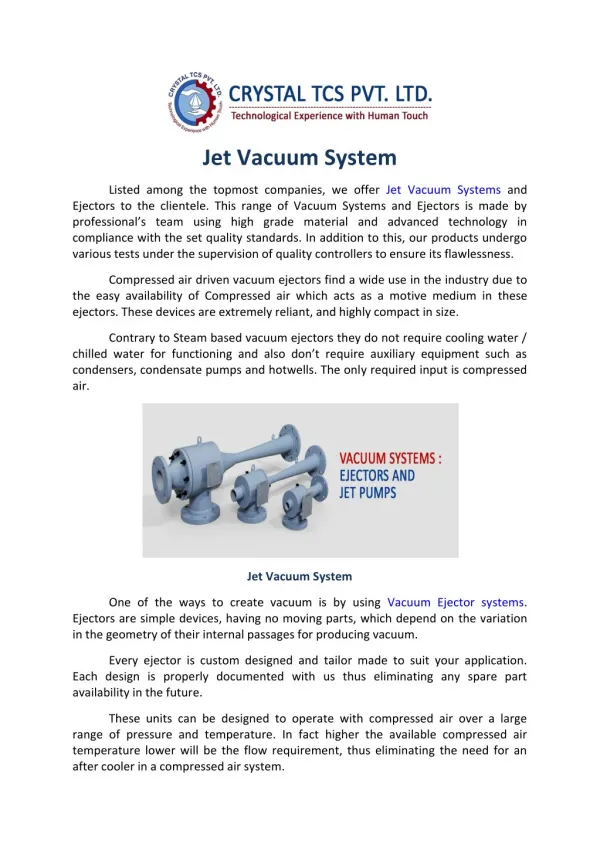
Vacuum solutions • For Ø90 cm pipe every 2 to 5m a turbo+roughing system • Roughing (mechanical): atm. to 10-2 torr; turbo: 10-2 to 10-6 torr • Vacuum line segmented with pneumatically operated gate valves • Cryogenic pumps on compressor and target chambers (~104 l/s) • Backup system on compressor/target chambers based on turbopumps (repair or regeneration of cryopumps)
Vibrations solutions • Laser interferometer for measuring the micro-motion between the 2 floors (laser and experimental areas) & for alignment of large optics • Large bellows in the beam line • Special stands for roughing pumps (w. damping springs) • Special supports for target chambers (based on polymer layers) • Cryopumps instead of turbo pumps
Other issues • Large flanges with windows, also large viewing windows on compressor/target chamber • Filters on exhausts for containing nuclear debris • Separate vacuum pumps for Target Positioner System, or instrument manipulator (eg. TIM at LANL)etc
Conclusions • Prerequisite for a good design is to identify and set the system parameters • Tight collaboration with laser and civil engineering groups • Learn from the experience of other facilities worldwide • Work closely with companies to deliver the right solution Thank you!