Download
1 / 6

E N D
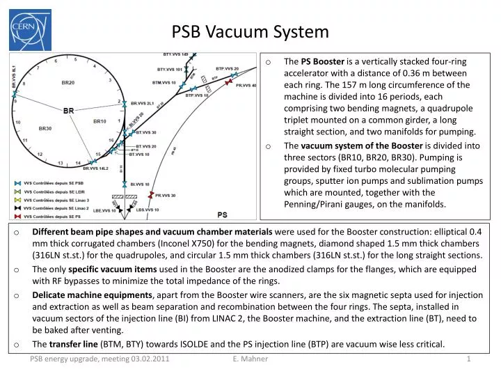
PSB Vacuum System • The PS Booster is a vertically stacked four-ring accelerator with a distance of 0.36 m between each ring. The 157 m long circumference of the machine is divided into 16 periods, each comprising two bending magnets, a quadrupole triplet mounted on a common girder, a long straight section, and two manifolds for pumping. • The vacuum system of the Booster is divided into three sectors (BR10, BR20, BR30). Pumping is provided by fixed turbo molecular pumping groups, sputter ion pumps and sublimation pumps which are mounted, together with the Penning/Pirani gauges, on the manifolds. • Different beam pipe shapes and vacuum chamber materials were used for the Booster construction: elliptical 0.4 mm thick corrugated chambers (Inconel X750) for the bending magnets, diamond shaped 1.5 mm thick chambers (316LN st.st.) for the quadrupoles, and circular 1.5 mm thick chambers (316LN st.st.) for the long straight sections. • The only specific vacuum items used in the Booster are the anodized clamps for the flanges, which are equipped with RF bypasses to minimize the total impedance of the rings. • Delicate machine equipments, apart from the Booster wire scanners, are the six magnetic septa used for injection and extraction as well as beam separation and recombination between the four rings. The septa, installed in vacuum sectors of the injection line (BI) from LINAC 2, the Booster machine, and the extraction line (BT), need to be baked after venting. • The transfer line (BTM, BTY) towards ISOLDE and the PS injection line (BTP) are vacuum wise less critical. E. Mahner
Modifications, impact for TE-VSC (1/3) • Magnets • General comment: minimize the amount of equipment to be removed from the Booster ring (not only magnets), to avoid surprises that cannot be judged today, otherwise it might become a major additional vacuum activity.... • Main units …an increase of the rms current of up to 10% (baseline scenario) would only dictate minor modifications of the cooling circuits without the need to remove the magnets from the machine. (no impact for VAC considered) • New information (A. Newborough): special injection and extraction magnets (BHZ 151,162): work is in progress for laminated retaining plates (to reduce the saturation) may involve to replace 8 vacuum chambers (2 magnets), re-shimming of the coils also needs chamber dismantling, BHZs to be removed from the tunnel (no impact for VAC considered so far) • Auxiliary ring magnets...not necessary to replace any... (no impact for VAC consid.) • Transfer line magnets...around 40% of the magnets (14-18) from the PSB to the PS will not be able to operate at 2 GeV... New optics presently under study • Largest impact for VAC • PS injection bumpers, correctors, quads ... under study E. Mahner
Modifications, impact for TE-VSC (2/3) • RF • Cavities ...the baseline is to replace amplifiers and not to touch the Booster cavities. Info M. Paoluzzi: working on a new system -> eventually replace 1 out of 3 cavities/ring (no impact for VAC considered so far, will change?) • Beam Intercepting Devices • Booster dump ...no spare, new design in progress • Beam stopper (BTP.STP10) ... either keep the vacuum tank and modify the absorber material or a new design (no impact for VAC considered, will change?) • Instrumentation • MTVs (2 new tanks) ...BT.MTV10 is housed in the BT.SMV10 tank. A new separated vacuum vessel for the screen will be build and placed downstream of the septum. BT.MTV20 is now inside BT.SMV20, build a new screen tank and place it downstream of the septum (impact for VAC) E. Mahner
Modifications, impact for TE-VSC (3/3) • Extraction, Transfer, PS Injection • PSB extraction • bumpers BE.BSW14L4, 15L1, 15L4 (ok) • kickers BE.KFA14L1 (complete new system) • septa BE.SMH (remove, modify, replace tank, reinstall.) • Booster Transfer (BT) • septa BT1.SMV10, BT4.SMV10 (remove, modify, replace tank, reinstall.), BT.SMV20 (remove, new magnet, reinstall.) • kicker BT1.KFA10, BT4.KFA10 (remove, new tank, new magnet, reinstall.), BT.KFA20 (no VAC impact) • PS injection • septum PI.SMH42 (complete new system) • kicker PI.KFA45, additional PI.KFA53 (under study) • Short summary • The Booster extraction kickers and recombination septa need a full redesign and new construction. The PS injection will be strongly affected: new vacuum chambers are needed for the septum. In the BT line, some vacuum chambers could be modified. In the booster transfer kickers BT1.KFA10 and BT4.KFA10 the ferrites will be changed. In the Booster transfer septum BT.SMV20 chambers have to be modified. • TE-VSC activities (dismantling, installation, leak testing,...) are requested and planned for all devices, except the extraction bumpers, which are ok for 2 GeV operation. E. Mahner
Manpower • Needs in man-weeks (mw) • Booster ring + transfer lines: 3 vacuum sectors + 11 septa and kickers (new vacuum chambers, dismantling, installation) + 18 magnets • 15 mw = 2 technicians (CP-B/C) • 18 mw= 2 technicians (industrial support), 2.5 days per device + 1 day per magnet • Beam instrumentation + beam intercepting devices • 4 mw (CP-B/C) • Other activities: follow-up, workshops, drawing office, etc. • 18 mw= 11 mw (CP-D) + 4 mw (CP-E/F) + 3 mw (CP-B/C) • Contingency • 10 mw industrial support 22.10.2010 E. Mahner
Conclusion • Impact for 2 GeV operation • The PS-Booster vacuum system and the associated transfer lines do not need an upgraded vacuum system for a 2 GeV operation. • No dynamic vacuum problems are anticipated in the PSB, but electron cloud induced pressure rises might become more significant in the PS. The latter should be addressed within "LIU-PS" • Activities for TE/VSC • Manpower needs for the energy upgrade of the PS Booster (TE-VSC-IVM cost estimation) done in 10/2010. If necessary, due to new activities, to be updated. Controls items (e.g. cabling cost due to change of PS injection) not yet included, also no increase of pumping speed (if required) • If we have to pay for all new vacuum chambers the cost will be more than 100 kCHF... • Consolidation and renovation is foreseen (pumps, gauges, valves, controls...) • Issues • Certainly, we need a complete leak detection (inventory), probably also a survey of all machine elements, before dismantling. • "Rough" evaluation about the collective dose for TE-VSC staff should be established. • What is the baseline for the machine layout today? Do the existing drawings (PSB + transfer lines) correspond with the installed equipment? Surprises are not excluded... Do we need a new, complete integration? Probably yes... E. Mahner