Download
1 / 33
330 likes | 458 Views
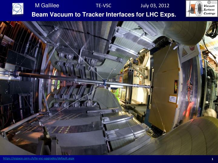
Beam Vacuum to Tracker Interfaces for LHC Exps. Overview. Introduction LHC Experimental Beampipes (LEB) Working Group at CERN Work of the LEB Mechanical Considerations Machine considerations Detector supports Bakeout Safety Future ideas Summary. Introduction.

E N D
Overview • Introduction • LHC Experimental Beampipes (LEB) Working Group at CERN • Work of the LEB • Mechanical Considerations • Machine considerations • Detector supports • Bakeout • Safety • Future ideas • Summary
Introduction • Tracker performance is critical to the operation of detectors. Tracker performance can be improved by a reduction in vacuum chamber diameter (to a limit), or reduction of material in the acceptance region. • This seminar will introduce the considerations for reducing the diameter of an experimental vacuum chamber, along with an overview of the materials and bakeout technologies currently available. • Future ideas and concepts will be introduced.
LEB at CERN - Mandate • The LEB Working Group was set up to consider new vacuum chamber geometries or supports in the LHC experimental areas. Its mandate is the following: • Define, set priorities and follow-up the activities for the consolidation and upgrade (phase I and II) of the experimental vacuum sectors in the LHC (Q1-Q1). • Mandate covers all topics to ensure the implementation and operation, new beam vacuum components and their associated supports, alignment, and access equipment. This includes definition of apertures, specification and follow-up of R&D and design. • The working group shall request approval from the [LHC Machine Committee]. It shall be composed of a member from each experimental collaboration, plus representatives from vacuum, survey, collimation, accelerator physics, safety and machine coordination.
LEB at CERN - Mandate • Requests so far: • Reduction in diameter of ATLAS central chamber from 58 mm ID to 47 mm ID; • Reduction in diameter of CMS central chamber from 58 mm ID to 43.4 mm ID; • Reduction in diameter of ALICE central chamber from 58 mm ID to 34.4 mm ID; • Reduction in diameter of LHCb UX85/1 region from 50 mm ID to 40 mm ID.
LEB at CERN - Methodology Machine Protection Machine Protection Background Background New Vacuum Chamber Geometry New Vacuum Chamber Geometry Injection Optics & Beam Dump Injection Optics & Beam Dump Aperture approval with LEB>LMC Aperture approval with LEB>LMC Impedance Heating Impedance Heating Collimation Collimation E-Cloud E-Cloud Positioning Tolerances Positioning Tolerances Dynamic Vacuum Dynamic Vacuum Mechanical Tolerances Mechanical Tolerances Aperture for n1 value Aperture for n1 value (Sector layout now defined) Static Vacuum Static Vacuum Stability Tolerances Stability Tolerances
Work of the LEB at CERN - Mechanical • The following mechanical considerations need to be addressed before defining the chamber aperture and layout: • Construction tolerances (sag, machining and assembly); • Experiment stability; • Installation tolerances. • Generally beryllium is used for the central experimental chambers. Experience has been gained with their construction; therefore more accurate prediction is possible.
Work of the LEB at CERN - Mechanical • Example of construction tolerances for the LHCb UX85/3 beryllium chamber (6m length):
Work of the LEB at CERN - Mechanical • Example of construction tolerances for the CMS central beryllium chamber (6.24m length): Chamber construction within +/- 0.5 mm
Work of the LEB at CERN - Mechanical • In terms of experiment stability, the stability of the caverns needs to be taken into account. The figure below shows stability of the CMS cavern over 5 years.
Work of the LEB at CERN - Mechanical • Position and stability can also be verified by nuclear interaction tomography. Below is a reconstructed image from ATLAS, verifying the beam position.
Work of the LEB at CERN - Mechanical • Positioning tolerances are given by survey. They are very dependant on the measuring system and the number of transfers that need to be made. Precision is generally between 1-2 mm depending on complexity of the network. Below is an example of the network for CMS.
Work of the LEB at CERN - Mechanical • More accurate tolerances have been possible due to improved operational knowledge; therefore a gain in physical aperture to the beam. Below is an example of the tolerances for CMS and ATLAS after installation in 2008 and again after review in 2011.
Work of the LEB at CERN - Machine • With the mechanical considerations addressed, the layout can now be analysed for aperture, vacuum, impedance, and machine protection.
Work of the LEB at CERN - Machine • With the given construction tolerances, the layout is defined and the aperture calculated. At CERN we use n1 sigma to define the beam size. This must remain higher in the experimental areas when compared with the rest of the machine to prevent aperture restriction. Below is the calculated aperture for ATLAS at injection. N1 sigma > 10, therefore not a restriction for the machine
Work of the LEB at CERN - Machine • With the layout frozen, impedance must be considered. For the new CMS central vacuum chamber, impedance was analysed. Below is the conclusion of this analysis. • Power loss increased by ~30% if radius reduced from 29mm to 21.7mm. CMS case is similar to ATLAS. • Longitudinal and transverse effective impedances increase significantly with the radius. Negligible with respect to the rest of the ring. The CMS case is again similar to the ATLAS case. • Taper angle 1.7deg has negligible impact on imaginary impedance. • Assumed that there are no bellows changes. New chamber presents no impedance issues
Work of the LEB at CERN - Machine • Now that the layout is defined, the vacuum profile needs to be analysed. Below is an analysis for the new CMS central chamber showing no difference between the old and new chambers.
Work of the LEB at CERN - Machine • The dynamic vacuum must also be considered. Below is an example of the analysis from CMS. • Vacuum stability (TAS to TAS): • Dynamic vacuum: • Synchrotron radiation • electron cloud after scrubbing (no multipacting) less than 10-10 mbar • Finally, machine protection, collimation, and injectionmust be discussed. It is generally accepted that these will be satisfactory, providing that that the n1 value is sufficiently high. Other machine protection issue such as kicker failures and TDI showers need to be considered for experiments such as ALICE and LHCb.
Detector Supports (LHCb example) Current Supports Section 2 and 3 stretched wires supports (fix): design optimized for best achievable transparency within schedule and for safety during alignment Section 4 supports (fixed and sliding): design optimized for assembly and rigidity Section 1 and 3 thin wires supports (x-y position): design optimized for transparency
Detector Supports (LHCb example) • LHCbcurrentlayout: • Support a sorce of background • 8 stainlesssteelrods and 8 cables • 2 aluminium collars • 2 vespel rings
Detector supports (LHCb example) • LHCb new layout: • Reduced background • Increasedtransparency • 8 carbon fibre rods • 8 Technoraropes • 2 berylliumcollars • 2 Celazole rings
Detector supports (LHCb example) Carbon Fibre Tube Rope Collar (alu prototype) CFRP rodtermination Ropewheel + alu pin Celazole interface ring
Detector supports (LHCb example) Transparency indicator: I=d/lwith l the radiation length and Characteristic length distribution for a rod Characteristic length distribution for a tube Factor of 15-20 Factor of 10
Detector supports (CMS Concept) • Concept is single piece collar mounted before final closure weld of the chamber. Stiffness and transparency are increased when compared to a two piece support collar Current collar Two piece Single piece
Safety Considerations Beryllium supports: The use of beryllium is subjected to some safety rules [EDMS 1173433, 1173433]. In particular, any friction must be avoided during commissioning between the beryllium collar and other contact faces in order to avoid any particle or dust generation. Aluminium inserts Polyimide foil Plastic target support
Bakeout • Three types of bakeout system: • Standard (removable) – allow 20 mm radial clearance and then remove if necessary. For areas with easy access or low activation. Example: ALICE, CMS, LHCb 20 mm
Bakeout • Three types of bakeout system: • Oven – slid in around vacuum chamber on guide rails. Example: CMS central chamber.
Bakeout • Three types of bakeout system: • In-situ– allow 5 mm radial clearance. Minimised equipment with Aerogel, and Kapton heaters for areas with limited access or high activation. Example: ATLAS
Bakeout • Aerogel (Pyrogel AR 5223, Silica, Tmax 650oC, density 110 kg/m3): • Single layer (approx. 5 mm) – as shown by the Figure below, at 250oC on the heater side, the opposite side would be around 100oC, which decreases to 60oC with two layers (10 mm) and 30oC with three (15 mm).
Future work (Supports) • Activation is a key issue for the access of personnel into the cavern. This is one area where we are extremely active in finding solutions. One concept of a motorised support system for the ATLAS forward regions is shown below. This would allow chamber alignment without personnel intervening
Future Work (Bakeout & Chambers) • Ideas for bakeout in the future include the following: • Rigid insulation – solid ceramic foam to allow mounting of detectors directly on the outside of the insulation. • Activation in lab – activation in the laboratory, transportation and installation under Neon. • Avoids need for long bellows and bakeout equipment; • Higher risk if NEG saturation occurs. • New chambers • Alternatives to beryllium in development for reasons of safety and manufacturability; • Current promising technologies are Metal Matrix Composites (MMCs), honeycomb and glassy carbon.
Summary • The LEB Working Group at CERN is currently re-analysing vacuum chamber apertures based on gained machine running knowledge. • Many aspects need to be considered before a reduction in chamber aperture. • The LHC experiments are constantly requesting more and more transparent supports. These needs are being met with new materials, including beryllium. • Activation is taken seriously and technologies that allow remote access are being developed. • The CERN Vacuum Group is currently investigating possible alternatives to beryllium for vacuum chamber materials. Promising technologies are MMCs, Glassy Carbon, Honeycomb structures.
Summary Merci! Thanks! Acknowledgements CERN LEB Working Group, particularlyAntje Behrens, Gloria Corti, Massimo Giovannozzi, Giulia Lanza, and from TE-VSC, Paul Cruikshank, CedricGarion, Louise Leduc, Hendrik Kos, Patrick Lepeule and Pedro Noguera (AVS)