Download
1 / 12
130 likes | 156 Views
ESRF VACUUM SYSTEM. R. Kersevan, Vacuum Group, Tech.Serv.Division, ESRF, Grenoble. ALBA-MaxLab Workshop on Vacuum Systems for Synchrotron Radiation Light Sources, Barcelona, 12-13 Sept 2005. ESRF Machine Parameters:. Energy, GeV 6

E N D
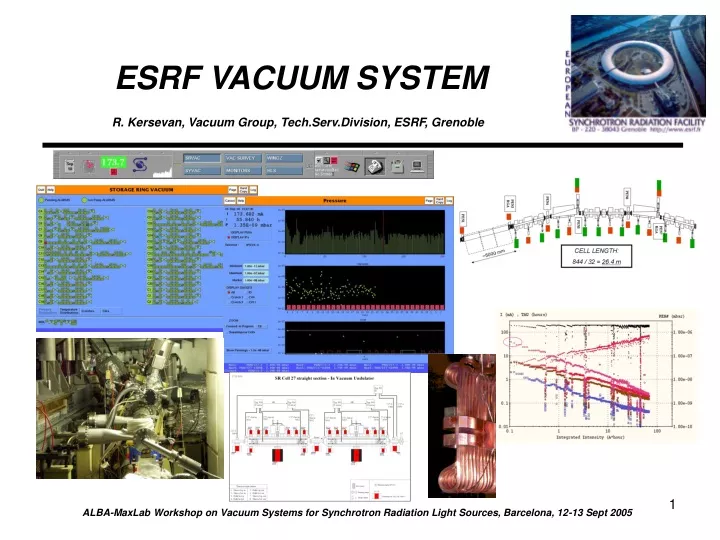
ESRF VACUUM SYSTEM R. Kersevan, Vacuum Group, Tech.Serv.Division, ESRF, Grenoble ALBA-MaxLab Workshop on Vacuum Systems for Synchrotron Radiation Light Sources, Barcelona, 12-13 Sept 2005
ESRF Machine Parameters: • Energy, GeV 6 • Filling modes uniform, 2x1/3, hybrid, single, 16-bunch, 4-bunch • Beam currents, mA 200 (multi-bunch); 90 (16-bunch); 15 (single-bunch) • Filling cycles per day 2 (multi-bunch), 4 (single, 16-bunch) • Circumference, m 844 • Symmetry 2x16 (hi-low/beta sections, 32 cells, 64 dipoles) • Dipole Field, T / bending radius, m 0.857 / 23.366 • Dipole radiation critical energy, keV 20.5 • Synchrotron radiation power, KW 982 (dipoles only) • RF frequency, MHz / RF stations / type 352 / 3 / normal-conducting, LEP-type cells • Number of straight sections and cells 32 • Length of straight section, m 5 (effective length available for ID segments) • Emittances: horizontal, vertical, nm 4.2, 0.190 (typical value, multi-bunch filling) Machine Operation: • Days of operation per year 287 (2005) • Scheduled hours in user mode (USM) 5472 (2004) • Number of shutdowns per year 5 (2x4week (Dec, Aug) + 3x10days (Mar, May, Oct)) • Number of machine-dedicated days (MDT) 1/week during operation, 4/machine re-start • Typical beam dose accumulated/run, A*hour 150-200 (depending on scheduled filling modes) • Beam availability 97.2% (2004) • Dead time for refills 0.75% (2004) • Dead time for failures, % / MTBF, hours 2.05% / 49.1 (2004)
Vacuum System Specifications and Data: • Vacuum chamber materials 316L(N), 6060 T6 extruded Alu, OFHC Cu, GlidCop, bi-metal explosion-bonding transitions • Flange types modified ConFlat (reduced flange-to-flange gap); Wheeler (on in-vac IDs) ; bi-metal (Atlas) • Pumping system ion-pumps (StarCell), NEG pumps (GP-series), Ti-sublimators, NEG-coatings • Number of ID sections available / used 28 / 28 (unavail. to IDs: cell 4 injection ; cell 5, 7, 25 RF) • Gate valves 46 manual w/RF ; 22 pneumatic w/RF ; 59+3 manual w/o RF (FE, IR-beamline) (VAT) • Number of in-air ID chambers 27 (some sections have >1 chamber) • Number of pumps per in-air ID 2 (120 l/s SIPs) • Number of in-vacuum IDs 8 (7x2000mm + 1x1600mm proto) • Number of pumps per in-vac 2000 SIPs: 8x60 l/s, 1x400 l/s ; NEG: 1xGP500 ; Ti-sublimator: 2x • Beam lifetimes, hours 80 (uniform), 60 (2x1/3), 6-7 (single, hybrid), 10 (16-bunch) • Number of pumps per standard cell 11 SIP: 2x400 l/s, 4x120 l/s, 2x60 l/s, 3x45 l/s (Varian StarCell) 11 NEG: 2xGP500, 9xGP200 (SAES) • Averaged pressure at t = 60 hours, mbar 1.4E-9 (2x1/3 filling mode) • Typical no. of machine vacuum interventions, y-1vented cells: 10; in-air IDs: 12; in-vacuum IDs: 2; other (leak- detections, cabling, injector accelerators vacuum): 25-30 • Support to beamlines at least one technician is assigned to each BL (machine work has priority) • Vacuum group staff 1x physicist, 2x engineers, 13x technicians, 1x secretary
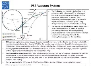
ESRF: STANDARD CELL IP/NEG DISTRIBUTIONAND LOCATION OF VACUUM GAUGES: PEN6 PEN3RGA PEN4 PEN1 PEN5 PEN7 RGA CELL LENGTH: 844 / 32 = 26.4 m ~5000 mm Ion pumps (Varian): ID:120 l/s ; CV4/CV11: 120 l/s; CV3/CV10/CV15: 45 l/s; dipoles: 60 l/s ; crotches: 400 l/s NEG pumps (SAES): crotches: GP500 ; elsewhere: GP200
Machine Status for RUN 05-4 (18/8 – 17/10/2005): NEG-COATED CHAMBERS: 10 mm ALU CV5073: 11x 15 mm ALU CV5073: 2x 15 mm ALU CV2093: 4x 10 mm SS CV5175: 1x Total NEG-coated length, m: 79.5 NO ADVERSE EFFECT ON RESISTIVE-WALL IMPEDANCE* - 0 - UN-COATED CHAMBERS: 15 mm SS CV5073: 6x 19 mm SS CV5073: 1x OTHER SS: 2x (3T-chamber + CV2000 AMPW @ C-15) - 0 - IN-VACUUM UNDULATORS: CV2000: 7x CV1600: 1x Minimum delivery gap, mm: 6 *T. Perron, “Single Bunch-Related Impedance Measurements on the ESRF Storage Ring", PhD thesis, November 2005, Université Joseph Fourier, Grenoble
Vacuum System Monitoring and Control 1: • Main software application: • SRVAC • control of all equipment: pumps, gauges, remote GVs • visualization of pressures, temperatures, and vacuum interlocks status
Vacuum System Monitoring and Control 2: Other applications have been developed during the years (Computing Service, Machine Diagnostic Group)… • VACUUM_SURVEY: • reference pressures are taken at end of MDT, and used to spot trouble points • detected many leaks ( mainly slow corrosion) at a very early stage • Beamloss “Cartography” MatLab application: • Useful for making links between beam losses and pressures around the ring during operation and MDT
Machine and BL Databases and Web Pages: Vacuum web page: Vacuum conditioning plots: Synopsis of machine sections:
Vacuum Conditioning of ID Chambers, RUN 05-4: Stored current • C-3: 15mm SS vented and re-baked • C-6: partially conditioned NEG/Alu 10mm from D15 • C-12: NEG/Alu 10mm from ID6 • C-19: Re-activation (no venting) of NEG/Alu 10mm • C-28: NEG/SS 10mm untouched lifetime
Recent Projects and Developments (some still underway…): • Commissioning of second NEG-coating tower (now) • Cryogenic in-vacuum undulator (in-house program, ID group) (2006) • SC in-vacuum undulator (collab. other labs, industry) (2006) • “ESRF-2” NEG-Coated vacuum chambers (already tested on Cell 6) RUN05-3 • NEG-coating and/or testing for other labs: SLS, Soleil, … (now) • Upgrade of 15 and 19 mm SS ID chambers with 10mm NEG-coated ones • New PLC, new system for monitoring of temperatures • More…
Bremsstrahlung Measurements of NEG-Coated Vacuum Chambers on ID6: • Each new NEG-coated CV5000 is pre-installed and pre-conditioned on ID6, where its bremsstrahlung level can be measured precisely (dedicated hutch). Very effective way of characterizing vacuum inside the ID chamber • Some chambers are pre-conditioned on dedicated vacuum group beamline (D15). Not yet clear whether it is effective or not Source: P.Berkvens, P.Colomp, ESRF Safety Group, “Radsynch2 Workshop”, ESRF 17-18/10/02
Presentation made thanks to contributions and work from all members of the vacuum group, machine and operation groups, safety group, mechanical engineering group.THANK YOU FOR YOUR ATTENTION!