Download
1 / 40
420 likes | 611 Views
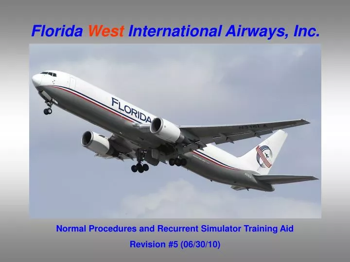
Florida West International Airways, Inc. Normal Procedures and Recurrent Simulator Training Aid Revision #5 (06/30/10). Introduction.

E N D
Florida West International Airways, Inc. Normal Procedures and Recurrent Simulator Training Aid Revision #5 (06/30/10)
Introduction • The following information is only a suggested outline and does not take the place of a thorough review of the your aircraft and company manuals as well as the GOM. The manuals are still the proper means to prepare for your training / checking session. • This training aid is for reference only. It will be revised periodically to ensure consistency with the B767 Flight Crew Operations Manual (FCOM), B767 Flight Crew Training Manual (FCTM) and the General Operations Manual (GOM). However, in the event of a conflict, the applicable manual is controlling.
Using This Training Aid • This Training Aid is set up to review in two ways. • Option 1– Left click the mouse to advance the slides. This method views each page of the training aid in order. • Option 2 - The following page contains a table of contents. Left click the mouse to advance to the table of contents. You can then view any page in the training aid by left clicking on the page name. To return to the table of contents, click on the blue arrow in the bottom corner of the page. • To stop viewing this training aid at anytime, right click on the mouse and select end show. • Limitations, Recall Items (Non-Normal Checklists) and Flight Profiles are set up as “flash cards.” To get the most out of this presentation you should say the answer or next item before advancing the slide to ensure you know each item.
Limitations Operational Limitations Non-AFM Operational Information RVSM Altimeter Cross Check Limits Weight Limitations Auto Flight Engine Engine Fuel System Reverse Thrust Flight Controls Navigation GPWS Look Ahead Alerting Crew Rest Module Recall Items (Non-Normal Checklists) Aborted Engine Start Airspeed Unreliable Cabin Altitude or Rapid Depressurization Dual Engine Failure Engine Fire or Severe Damage or Separation Engine Limit or Surge or Stall Normal Profiles Takeoff ILS Approach Non-ILS (Instrument Approach Using V/S) Go-Around and Missed Approach Non-Normal Profiles (1 Engine) Takeoff ILS Approach Non-ILS (Instrument Approach Using V/S) Go-Around and Missed Approach Simulator Training/Checking Tips General Items Other Non-Normals Rejected Takeoff Steep Turns Stalls Cabin Altitude or Rapid Depressurization Non-ILS Approaches Airspeed Unreliable Engine Failure or Fire at V1 or Just After Liftoff Table of Contents
Operational Limitations Runway Slope +/-2% Maximum Operating Altitude 43,100 feet pressure altitude Maximum Takeoff and Landing Altitude 9,500 feet pressure altitude Maximum Takeoff and Landing Tailwind Component 15 knots
Non-AFM Operational Information Note: The following items are not AFM limitations, but are provided for flight crew information. Turbulent air penetration speed is 290 KIAS /.78 Mach The navigation and display system Does not support operations at latitudes greater than 87o North or South.
The maximum allowable in-flight difference between Captain and First Officer altitude displays for RVSM operation is 200 feet. RVSM Altimeter Cross Check Limits Standby altimeter limitation Standby altimeters do not meet altimeter accuracy requirements of RVSM. Maximum allowable in-flight difference–Captain & First Officer Altimeter The maximum allowable on-the-ground differences between Captain and First Officer altitude displays for RVSM operation are
Weight Limitations Maximum Weight Limitations Weights Kilograms 187,333 Maximum Taxi Weight (MTW) 186,880 Maximum Take Off Weight (MTOW) 147,871 Maximum Landing Weight (MLW) 140,160 - (141,657 with Winglets) Maximum Zero Fuel Weight (MZFW) Other Weight Restrictions Note: These weights may be further restricted by field length limits, climb limits, tire speed limits, brake energy limits, obstacle clearance, or enroute and landing requirements.
Do not use the autopilot below 100 ft. Radio Altitude at airport pressure altitudes above 8400 ft. Auto Flight Use After Takeoff After takeoff, the autopilot must not be engaged below 200 feet AGL. High Altitude Airport Use Use of Trim Use of aileron trim with the autopilot engaged is prohibited. Maximum allowable wind speeds when landing weather minima are predicated on autoland operations
Continuous ignition must be on (engine start selector in the CONT position) while operating in severe turbulence. Note: Continuous ignition is automatically provided in icing conditions when engine anti-ice is on. Engine Limitation With Turbulence Engine Vibration Flight Crew shall not blank engine vibration display during takeoff.
The minimum inflight fuel tank temperature is 3oC (5oF) above the freeze point of the fuel being used (Jet A: -40oC, Jet A-1: -47oC) The center tank may contain up to 10,000 kilograms of fuel with less than full main tanks provided center tank fuel weight plus actual zero fuel weight does not exceed the maximum zero fuel weight, and center of gravity limits are observed. The use of JP-4 or Jet B is prohibited. Engine Fuel System Minimum Temperature Maximum Temperature The maximum fuel temperature is 49oC (120oF). Fuel Type Limitation Center Tank
Reverse Thrust Reverse thrust is for ground use only.
Flight Controls The maximum altitude for flap extension is 20,000 feet. Avoid rapid and large alternating control inputs, especially in combination with large changes in pitch, roll, or yaw (e.g. large side slip angles) as they may result in structural failure at any speed, including below VA.
Do not operate under IFR or at night into airports north of 73o North or south of 60o South Latitude whose navigation aids are referenced to magnetic north. Navigation
The use of look-ahead terrain alerting and terrain display functions is prohibited within 15 nm of takeoff, approach or landing at an airport not contained in the GPWS terrain database. Refer to Honeywell Document 060-4267-000 for airports and runways contained in the installed GPWS terrain database. Ground Proximity Warning System (GPWS) Look-Ahead Alerting Do not use the terrain display for navigation.
Crew Rest Module When the Crew Rest Module is required by the Federal Aviation Regulations (4-pilot crew), it is restricted to use by the essential flight crew only (pilot/co-pilot). The Crew Rest Module is also restricted to in-flight use only and is therefore not to be occupied during takeoff and landing.
Aborted Engine StartQRH 7.1 1 FUEL CONTROL switch (affected side) .................... CUT OFF
Airspeed UnreliableQRH 10.1 1 Check the pitch attitude and thrust. 2 If pitch attitude or thrust is not normal for phase of flight: Autopilot disengage switch ………………………………...…Push Autothrottle disconnect switch……………………………......Push F/D switches (both)……………………………………………..OFF Establish normal pitch attitude and thrust setting for phase of flight.
CABIN ALTITUDEorRapid DepressurizationQRH 2.1 1 Don the oxygen masks 2 Establish crew communications 3 Ground Call & Crew Rest Alert Switch..........................................Push 4 Check the cabin altitude and rate 5 If the cabin altitude is uncontrollable: Without delay, descend to the lowest safe Altitude or 10,000 feet, whichever is higher. To descend: Move the thrust levers to idle Extend the speedbrakes If structural integrity is in doubt, limit airspeed and avoid high maneuvering loads Descend at VMO/MMO
Dual Engine FailureQRH 7.2 1 ENG START selectors (both)..............................................................FLT 2 Thrust Levers (both)...........................................................................IDLE 3 FUEL CONTROL switches (both)..............................CUTOFF, then RUN 4 If engine appears stalled or EGT approaches the Standby Engine Indicator placard limit: Repeat the above step as needed.
ENGINE FIREorEngine Severe Damage or SeparationQRH 8.2 1 A/T ARM switch.................................................................................OFF 2 Thrust lever (affected side).......................Confirm..............................Idle 3 FUEL CONTROL switch (affected side)...Confirm.....................CUTOFF • Engine Fire Switch (affected side)............Confirm..............................Pull • If the engine fire warning light is illuminated: Engine fire switch.........Rotate to the stop and hold for 1 second If after 30 seconds the engine fire warning light stays illuminated: Engine fire switch..... Rotate to the other stop and hold for 1 second
Engine Limit or Surge or StallQRH 7.6 1 A/T ARM switch .............................................................................. OFF 2 Thrust lever ............Confirm ............................................... Retard until indications remain within normal limits or the thrust lever is at idle
Pilot Flying – Blue Text Pilot Monitoring – Green Text Note: For an immediate turn after takeoff, maintain initial climb speed with takeoff flaps while maneuvering. Follow AFDS bank limits Engage the autopilot after a roll mode and VNAV are engaged. Initial climb speed • V2+15 to V2+25 knots Acceleration height • Select VNAV • Retract flaps on schedule • PM – “1000 feet” • PF – “VNAV” or “FLCH” • PF – “Center Command” • PM – “Thrust set” • PF – “Checked” If takeoff to be made by FO: • PF(CA) – “You have control” • PM(FO) – “I have control” • At this point, the FO becomes PF and the Captain becomes PM VR • Rotate • PM – “Rotate” Takeoff –FWIA SOP (2 Engine) Thrust set: • Manually advance thrust to 70% N1 • Allow engines to stabilize (max 2 sec) • Engage autothrottle • PF – “N1” Above 400 feet RA • Select roll mode • PM – “400 feet” • PF – “LNAV” or “Heading select” Ensure target N1 is set by 80 knots Monitor airspeed Maintain light forward pressure PM – “80 knots” PF – “Checked” V1 • PM – “V1” Flaps up • Do the After Takeoff checklist • PF – “After Takeoff checklist” • PM – “After Takeoff checklist complete” Positive rate of climb • Retract gear • PM – “Positive Rate” • PF – “Gear up”
Pilot Flying – Blue Text Pilot Monitoring – Green Text Approach Intercept heading • Flaps 5 • PF – “Flaps 5” Flaps 1 PF – “Flaps 1” On RADAR vectors • HDG SEL • Pitch mode (as needed) Enroute to fix • LNAV or other roll mode • VNAV or other pitch mode Flaps 5 PF – “Flaps 5” At 100 feet above DA in IMC • PM – “Approaching Minimums” • PF – “Checked” 1000 feet above TDZE • PM – “1000 feet, cleared (not cleared) to land” • PF -- Checked At DA in IMC • PM – “Minimums” and “Approach Lights”, “Runway Lights” or “Runway” in sight; Otherwise “No Contact” • PF – “Continuing”, “Landing” or “Go-Around” ILS Approach–FWIA SOP (2 Engine) Intercept Heading • ILS tuned and identified • LOC and G/S pointers displayed • Arm APP mode Glideslope intercept • Landing flaps • Set missed approach altitude • Do the landing checklist • PF – “Flaps 30” • PF – “Landing checklist” • PM – “Landing checklist complete” Localizer capture • Final approach course heading 500 feet above TDZE • Verify autoland status • PM – “500 feet” • PF “Checked” Glideslope alive • Gear down • Flaps 20 • Arm speedbrake • PM – “Glideslope Alive” • PF – “Gear down” • PF – “Flaps 20” Fix • (LOM, MKR, DME) • Verify crossing altitude • PM – (In IMC) “___ (Name of Fix) Altimeters and Instruments cross checked” 100 feet above TDZE in IMC • PM – “100 feet” and “Runway in Sight” or “No Contact” • PF – “Landing” or “Go-around”
Pilot Flying – Blue Text Pilot Monitoring – Green Text Approach Intercept heading • Flaps 5 • PF – “Flaps 5” Flaps 1 PF – “Flaps 1” Flaps 5 PF – “Flaps 5” FAF • PM – (In IMC) “___ (Name of Fix) Altimeters and Instruments cross checked” 500 feet above TDZE • PM – “500 feet” • PF – “Checked” Instrument Approach Using V/S – FWIA SOP (2 Engine) On RADAR vectors • HDG SEL • Pitch mode (as needed) Intercept Heading • Arm LNAV or appropriate roll mode Enroute to fix • LNAV or other roll mode • VNAV or other pitch mode Descend to MDA(H) • Set V/S • Do the Landing checklist • PF – “Landing checklist” • PM – Landing checklist complete 1000 feet above TDZE • PM – “1000 feet, cleared (not cleared) to land” • PF – “Checked” At 100 feet above MDA(H) • Set missed approach altitude in MCP • PM – “Approaching Minimums” • PF – “Checked” Inbound (Approximately 2 NM) • Gear down • Flaps 20 • Arm speedbrake • Set MDA(H) • Landing flaps • PF – “Gear down” • PF – “Flaps 20” • PF – “Flaps 30” At MDA(H) • Intercept landing profile and disengage autopilot and disconnect autothrottle • PM – “Minimums” and “Runway in Sight” or “No Contact” • PF – “Landing” or “Go-around”
Pilot Flying – Blue Text Pilot Monitoring – Green Text For a manual go-around: • Rotate manually • Select or verify go-around thrust • Engage autopilot as needed Go-Around and Missed Approach – FWIA SOP (2 Engine) Acceleration height • Set speed for planned flap setting • Select CLB thrust • Retract flaps on schedule • PM – “1000 feet” • PF – “Set Speed __” • PF – “Climb thrust” Initiation • Push GA, flaps 20 • Verify go-around attitude • Verify or adjust thrust as needed • Positive rate of climb – gear up • PF – “Go-Around” • PF – “Flaps 20” • PM – “Positive rate” • PF – “Gear up” After planned flaps set and at or above flap maneuvering speed • Select FLCH or VNAV • Verify altitude capture • Do the After Takeoff checklist • PF – “Flight Level Change” or “VNAV” • PF – “Center Command” • PF – “After Takeoff checklist” • PM – “After Takeoff checklist complete” Above 400 feet RA • Select roll mode • Verify missed approach altitude set • Verify route tracking • PM – “400 feet” • PF – “LNAV” or “Heading Select”
Pilot Flying – Blue Text Pilot Monitoring – Green Text Note: For an immediate turn after takeoff, maintain initial climb speed with takeoff flaps while maneuvering. Follow AFDS bank limits Engage the autopilot after a roll mode and FLCH are engaged. Initial climb speed • V2 to V2+15 knots Flaps up • At flaps up speed, select FLCH and select or verify CON thrust • Do the NNC (as needed) • Do the After Takeoff checklist • PF – “Flight Level Change” • PF – “Set Maximum Continuous Thrust” • PF – “Center Command” • PF – “After Takeoff checklist” • PM – “After Takeoff checklist complete” • PM – “Thrust set” • PF – “Checked” If takeoff to be made by FO: • PF(CA) – “You have control” • PM(FO) – “I have control” • At this point, the FO becomes PF and the Captain becomes PM VR • Rotate • PM – “Rotate” Takeoff –FWIA SOP (1 Engine) Thrust set: • Manually advance thrust to 70% N1 • Allow engines to stabilize (max 2 sec) • Engage autothrottle • PF – “N1” Above 400 feet RA • Select roll mode • PM – “400 feet” • PF – “LNAV” or “Heading select” • PM – Declare emergency Acceleration height • Select V/S 0 to +200 fpm • Retract flaps on schedule • PM – “1000 feet” • PF – “Set Vertical speed + ____” • PF – “Set Speed __” Ensure target N1 is set by 80 knots Monitor airspeed Maintain light forward pressure PM – “80 knots” PF – “Checked” V1 • PM – “V1” Positive rate of climb • Retract gear • PM – “Positive rate” • PF – “Gear up”
Pilot Flying – Blue Text Pilot Monitoring – Green Text Approach Intercept heading • Flaps 5 • PF – “Flaps 5” Flaps 1 PF – “Flaps 1” On RADAR vectors • HDG SEL • Pitch mode (as needed) Enroute to fix • LNAV or other roll mode • VNAV or other pitch mode Flaps 5 PF – “Flaps 5” At 100 feet above DA in IMC • PM – “Approaching Minimums” • PF – “Checked” 1000 feet above TDZE • PM – “1000 feet, cleared (not cleared) to land” • PF -- Checked At DA in IMC • PM – “Minimums” and “Approach Lights”, “Runway Lights” or “Runway” in sight; Otherwise “No Contact” • PF – “Continuing”, “Landing” or “Go-Around” ILS Approach–FWIA SOP (1 Engine) Intercept Heading • ILS tuned and identified • LOC and G/S pointers displayed • Arm APP mode Glideslope intercept • Set missed approach altitude • Do the landing checklist • PF – “Landing checklist” • PM – “Landing checklist complete” Localizer capture • Final approach course heading 500 feet above TDZE • Verify autoland status • PM – “500 feet” • PF “Checked” Glideslope alive • Gear down • Flaps 20 (landing flaps) • Arm speedbrake • PM – “Glideslope Alive” • PF – “Gear down” • PF – “Flaps 20” Fix • (LOM, MKR, DME) • Verify crossing altitude • PM – (In IMC) “___ (Name of Fix) Altimeters and Instruments cross checked” 100 feet above TDZE in IMC • PM – “100 feet” and “Runway in Sight” or “No Contact” • PF – “Landing” or “Go-around”
Pilot Flying – Blue Text Pilot Monitoring – Green Text Approach Intercept heading • Flaps 5 • PF – “Flaps 5” Flaps 1 PF – “Flaps 1” On RADAR vectors • HDG SEL • Pitch mode (as needed) Flaps 5 PF – “Flaps 5” Enroute to fix • LNAV or other roll mode • VNAV or other pitch mode FAF • PM – (In IMC) “___ (Name of Fix) Altimeters and Instruments cross checked” 500 feet above TDZE • PM – “500 feet” • PF – “Checked” Instrument Approach Using V/S – FWIA SOP (1 Engine) Intercept Heading • Arm LNAV or appropriate roll mode Descend to MDA(H) • Set V/S • Do the Landing checklist • PF – “Landing checklist” • PM – Landing checklist complete 1000 feet above TDZE • PM – “1000 feet, cleared (not cleared) to land” • PF – “Checked” At 100 feet above MDA(H) in IMC • Set missed approach altitude in MCP • PM – “Approaching Minimums” • PF – “Checked” Inbound (Approximately 2 NM) • Gear down • Flaps 20 (landing flaps) • Arm speedbrake • Set MDA(H) • PF – “Gear down” • PF – “Flaps 20” At MDA(H) • Intercept landing profile and disengage autopilot and disconnect autothrottle • PM – “Minimums” and “Runway in Sight” or “No Contact” • PF – “Landing” or “Go-around”
Pilot Flying – Blue Text Pilot Monitoring – Green Text For a manual go-around: • Rotate manually • Select or verify go-around thrust • Engage autopilot as needed Go-Around and Missed Approach – FWIA SOP (1 Engine) Acceleration height • Set speed for planned flap setting • Retract flaps on schedule • PM – “1000 feet” • PF – “Set Speed __” Initiation • Push GA, flaps 5 • Verify go-around attitude • Verify or adjust thrust as needed • Positive rate of climb – gear up • PF – “Go-Around” • PF – “Flaps 5” • PM – “Positive rate” • PF – “Gear up” After planned flaps set and at or above flap maneuvering speed • Select FLCH or VNAV • Select CON thrust • Verify altitude capture • Do the After Takeoff checklist • PF – “Flight Level Change” • PF – “Set Maximum Continuous Thrust” • PF – “Center Command” • PF – “After Takeoff checklist” • PM – “After Takeoff checklist complete” Above 400 feet RA • Select roll mode • Verify missed approach altitude set • Verify route tracking • PM – “400 feet” • PF – “LNAV” or “Heading Select”
General Items • On time - allow plenty of time (flat tire, traffic, etc.) to travel to Alteon . You need to be at least on time or preferably, early for the briefing. • Required Equipment - be sure to have all required pilot flight equipment as outlined in the GOM 6-1 (treat this as a real flight). • Manuals – the QRH is required, an FCOM is suggested. Be sure all manuals in your possession are current. • Medical and Certificate - just like on a flight, they must be in your possession and current. • Dress and Grooming - should be professional and appropriate to the event. Since the FAA may observe any training or checking, be sure to look the part. • Area of Responsibility – All training and checking will begin with a briefing from your instructor. You will be expected to know your flows and “Area of Responsibility” in accordance with FCOM Normal Procedures.
Other Non-Normals • You need to be familiar with the layout and use of the Non-Normal Checklist Section of the QRH. • Although the following Non-Normal Checklists do not contain any Recall Items, familiarization with these checklists will be helpful. • Engine Failure or Shutdown NNC.7.10 • Unscheduled Stabilizer Trim NNC.9.24
Steep Turns • During steep turns the Pilot Monitoring (PM) is no longer allowed to call out that you are approaching the 180 degree point. • Consider using the following procedure: • Engage the autopilot and autothrottles • Select “Heading Hold” prior to starting the turn. • Set your heading bug prior to starting the turn to the desired heading. • Disconnect the autopilot and auto throttles then start the turn. • Reference FCTM 7.18 & 7.19
Stalls • The Instructor will provide the speeds and power settings. • The key to an easy recovery from the stall sequence is the IVSI. Keep it in your scan and as close to 0 as possible. • Review pages 7.9 thru 7.17 in the FCTM.
CABIN ALTITUDEorRapid Depressurization • Accomplish Recall Items • After going on oxygen and establishing communications (you will not be able to talk to ATC if you have not selected oxygen on your mic selector switch), you must descend to a lower altitude. • Prior to starting your emergency descent try to contact ATC and obtain a clearance to descent to the 10,000 feet or the MEA, whichever is higher. However, if you are unable to contact ATC or the risk for the depressurization is greater than the risk related to a descent without clearance, descend immediately. • Be familiar with the Loss of Pressurization guidance (GOM section 7.6) and the Enroute Contingency guidance (GOM section 8.5). • Set the ProperDescent Altitude (MEA or 10,000’ whichever is higher). SelectFlight Level Change, move the Thrust Levers toIdle, and extend the Speedbrakes. • This is the time to determine if the aircraft has structural damage. If there is possible structural damage, maintain current speed. If no damage to the aircraft, set max speed for descent and call for the checklist. • At 10,000’ oxygen masks are no longer required. (FAR 121.333)(b).
Non-ILS Approaches • These approaches are what we have historically called VOR, ADF, BC, and LOC approaches. • The FCTM (page 5.48) details a new procedure when runway in sight and leaving MDA. Per the FWIA FCOM page NP.21.46, use of this procedure is at the pilot’s discretion. • Autopilot Disengage (optional at MDA, must be disconnected by 50 ft below MDA) • Autothrottle Disconnect (use thrust lever switch, not MCP switch) • PM - turn both F/D switches OFF, then place the PM’s F/D ON. • In the event of a missed approach when GA is engaged, the PF’s command bars will reappear and the autothrottles will reengage. At altitude capture if you have not turned on the PF’s flight director switch their command bars will disappear. • For all Non-ILS approaches the PF must brief the PM on the AFDS procedures he intends to use • No limitation to monitor raw data during a VOR approach • Recommend monitor because simulator does not have GPS Navigation. • Monitoring raw data will assist you in confirming your approach is on track. • Missed Approach Point • Note the distance to the MAP on the chart. Do not continue approach past this point. • Consider manually or remotely tuning both VOR’s • For all Non-ILS approaches, carefully review lighting to ensure landing on the proper runway.
Airspeed Unreliable • Difficult situation to realize • Excessive pitch command on F/D is usually the first clue • Review QRH page 10.4 for other indicators • Remember the Recall Items on the Non-Normal Checklist • Remove unwanted pitch commands • Use standby instruments • Other tools • Groundspeed display on the HSI • If you can depressurize the aircraft you have altitude and vertical speed information on the cabin pressurization panel. • Below 2,500 feet AGL, the radio altimeters will work. • All lateral navigation and glideslope information should be unaffected.
Engine Fire or Failure at V1 or Just After Liftoff • Ensure the aircraft is under control and on autopilot before starting applicable Non-normal checklist • Identify and Delegate • Recall Items (if applicable) - PM • Complete the Non-normal checklist - PM • Complete the after takeoff checklist – PM • Evaluate the Situation – Check weather and landing weight • Set the FMS for the approach - PM • Tune and identify the radios - PM • Set the airspeed bugs – PM • Transfer and Brief – Formally transfer aircraft to PM • Normal approach briefing • Single engine items – (Flaps 20, trim intentions, missed approach) • Transfer control back and call for the Approach Checklist
Summary • The purpose of this training aid is to provide Florida West Flight Crewmembers with a tool to study and review aircraft limitations, recall items and Company Standard Operating Procedures • If you find any inconsistencies or have any suggestions on how to improve this aid, please contact the Director of Training, the Chief Pilot or the Director of Flight Operations.