Download

1 / 47
550 likes | 839 Views
Pipelining. Adding registers along a path split combinational logic into multiple cycles increase clock rate increase throughput increase latency. Pipelining. Delay, d, of slowest combinational stage determines performance clock period = d

E N D
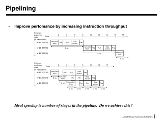
Pipelining • Adding registers along a path • split combinational logic into multiple cycles • increase clock rate • increase throughput • increase latency Pipelining and Retiming 1
Pipelining • Delay, d, of slowest combinational stage determines performance • clock period = d • Throughput = 1/d : rate at which outputs are produced • Latency = n•d : number of stages * clock period • Pipelining increases circuit utilization • Registers slow down data, synchronize data paths • Wave-pipelining • no pipeline registers - waves of data flow through circuit • relies on equal-delay circuit paths - no short paths Pipelining and Retiming 2
When and How to Pipeline? • Where is the best place to add registers? • splitting combinational logic • overhead of registers (propagation delay and setup time requirements) • What about cycles in data path? • Example: 16-bit adder, add 8-bits in each of two cycles Pipelining and Retiming 3
Retiming • Process of optimally distributing registers throughout a circuit • minimize the clock period • minimize the number of registers Pipelining and Retiming 4
Retiming (cont’d) • Fast optimal algorithm (Leiserson & Saxe 1983) • Retiming rules: • remove one register from each input and add one to each output • remove one register from each output and add one to each input Pipelining and Retiming 5
Optimal Pipelining • Add registers - use retiming to find optimal location 10 13 7 8 6 5 Pipelining and Retiming 6
Optimal Pipelining • Add registers - use retiming to find optimal location 10 13 7 8 6 5 10 13 7 8 6 5 Pipelining and Retiming 7
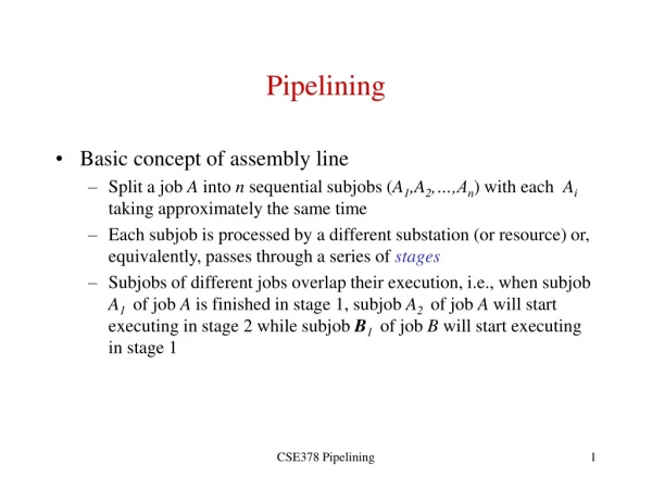
Example - Digital Correlator • yt = d(xt, a0) + d(xt-1, a1) + d(xt-2, a2) + d(xt-3, a3) • d(xt, a0) = 0 if x a, 1 otherwise (and passes x along to the right) yt + + + host d d d d a0 a1 a2 a3 xt Pipelining and Retiming 8
+ + + host d d d d Example - Digital Correlator (cont’d) • Delays: adder, 7; comparator, 3; host, 0 cycle time = 24 Pipelining and Retiming 9
+ + + host d d d d + + + host d d d d Example - Digital Correlator (cont’d) • Delays: adder, 7; comparator, 3; host, 0 cycle time = 24 cycle time = 13 Pipelining and Retiming 10
0 0 0 0 0 0 7 7 7 7 7 7 7 7 7 0 0 0 0 0 0 0 1 0 1 1 1 1 1 1 1 0 0 1 2 1 3 3 3 3 3 3 3 3 3 3 3 3 Retiming: One Step at a Time 0 0 0 0 0 1 0 0 1 Pipelining and Retiming 11
0 1 0 1 1 1 7 7 7 7 7 7 7 7 7 0 0 0 0 0 0 0 0 0 1 0 0 1 1 2 0 0 0 1 1 1 3 3 3 3 3 3 3 3 3 3 3 3 Retiming: One Step at a Time (cont’d) 0 0 0 1 0 0 and after a few more . . . 1 0 0 Pipelining and Retiming 12
Retiming Algorithm • Representation of circuit as directed graph • nodes: combinational logic • edges: connections between logic that may or may not include registers • weights: propagation delay for nodes, number of registers for edges • path delay (D): sum of propagation dealys along path nodes • path weight (W): sum of edge weights along path • always > 0, no asynchronous feedback • Problem statement • given: cycle time, T, and a circuit graph • adjust edge weights (number of registers) so that all path delays < T, unless their path weight 1, and the outputs to the host are the same (in both function and delay) as in the original graph Pipelining and Retiming 13
Retiming Algorithm Approach • Compute path weights and delays between each pair of nodes • W and D matrices • Choose a cycle time T • Determine if it is possible to assign new weights so that all paths with delays greater than T have a weight that is 1 or greater (use linear programming) • Choose a smaller cycle time and repeat until the smallest T is found Pipelining and Retiming 14
v7 v6 v5 0 0 7 7 7 0 0 0 0 0 0 vh 1 1 1 1 3 3 3 3 v4 v1 v2 v3 Computing W and D • W matrix: number of registers on path from u v • D matrix: total delay along path from u v W h 1 2 3 4 5 6 7 h 0 1 2 3 4 3 2 1 1 0 0 1 2 3 2 1 0 2 0 1 0 1 2 1 0 0 3 0 1 2 0 1 0 0 0 4 0 1 2 3 0 0 0 0 5 0 1 2 3 4 0 0 0 6 0 1 2 3 4 3 0 0 7 0 1 2 3 4 3 2 0 D h 1 2 3 4 5 6 7 h 0 3 6 9 12 16 13 10 1 10 3 6 9 12 16 13 10 2 17 20 3 6 9 13 10 17 3 24 27 30 3 6 10 17 24 4 24 27 30 33 3 10 17 24 5 21 24 27 30 33 7 14 21 6 14 17 20 23 26 30 7 14 7 7 10 13 16 19 23 20 7 Pipelining and Retiming 15
Computing W and D • W[u,v] = number of registers on the minimum weight path from u v • Any retiming changes the weight of all paths by the same constant • i.e. Retiming cannot change which is the minimum weight path • D[u,v] = maximum delay over all paths with W[u,v] registers • Retiming does not affect D[u,v] • These matrices contain all the required register and delay information • If retiming removes all registers from the path u v,then D[u,v] is the largest delay path that results Pipelining and Retiming 16
Retiming: Problem Formulation • r(v): number of registers pushed through a node in the forward direction • wnew(u, v) = wold(u, v) + r(u) - r(v) • Problem statement • r(vh) = 0 (host is not retimed) • wnew(u, v) = wold(u, v) + r(u) - r(v) 0, for all u, v • r(u) - r(v) - wold(u, v) (no negative registers!) • For all D[u,v] > Tclk, wnew(u, v) = wold(u, v) + r(u) - r(v) 1 • r(u) - r(v) - wold(u, v) + 1 (every long path has at least 1 reg) • Difference constraints like this can be solved by generating a graph that represents the constraints and using a shortest path algorithm like Bellman-Ford to find a set of r(v) values that meets all the constraints • The value of r(v) returned by the algorithm can be used to generate the new positions of the registers in the retimed circuit Pipelining and Retiming 17
1 0 1 0 7 7 7 7 7 7 0 0 0 0 0 0 1 0 1 1 1 0 1 1 3 3 3 3 3 3 3 3 Retimed Correlator 0 0 0 r = 0 r = 1 r = 2 1 0 0 r = 2 r = 0 r = 1 r = 1 r = 2 Pipelining and Retiming 18
Extensions to Retiming • Host interface • add latency • multiple hosts • Area considerations • limit number of registers • optimize logic across register boundaries • peripheral retiming • incremental retiming • pre-computation • Generality • different propagation delays for different signals • widths of interconnections Pipelining and Retiming 19
a D Q c a x D Q x b d d b D Q a D Q a x D Q b x b D Q D Q c c D Q Retiming examples • Shortening critical paths • Create simplification opportunities Pipelining and Retiming 20
+ + + host d d d d Digital Correlator Revisited • Optimally retimed circuit (clock cycle 13) • How do we know this is optimal? • Max-Ratio Theorem: Tc Dcycle/Rcycle for all cycles in circuit • Dcycle = total delay on cycle, including register tpd, tsu • Rcycle = number of registers on cycle • We know we can never do better than this • Can’t always do this well Pipelining and Retiming 21
Going Faster: C-slow’ing a Circuit • Replace every register with C registers • Now retime: (clock cycle now 7) + + + host d d d d + + + host d d d d Pipelining and Retiming 22
C-slow’ing a Circuit • Note that we get one value every c clock cycles • But clock period decreases • Throughput remains the same at best • The trick: Interleave data sets • Example: Stereo audio • Interleave the data for the two channels • Doubles the throughput! + + + host d d d d Pipelining and Retiming 23
Using C-Slowing For Time-Multiplexing • Clock period is for this circuit is 40 [2+10+5+5+10+5+3] • Min clock period after pipelining/retiming is at best 25 • Max ratio cycle: [2+10+5+5+3]/1 mult: 10, add: 5, Tpd: 2, Tsu: 3, Th: 1 Pipelining and Retiming 24
Using C-Slowing For Time-Multiplexing • Pipelined/Retimed Circuit • Let’s reschedule for 2 clock cycles/iteration mult: 10, add: 5, Tpd: 2, Tsu: 3, Th: 1 Pipelining and Retiming 25
Using C-Slowing For Time-Multiplexing • Start by C-slowing mult: 10, add: 5, Tpd: 2, Tsu: 3, Th: 1 Pipelining and Retiming 26
Using C-Slowing For Time-Multiplexing • Now retime • Note: 3 multiplers are red, 3 are white: share 2 adders are red, 2 are white: share mult: 10, add: 5, Tpd: 2, Tsu: 3, Th: 1 Pipelining and Retiming 27
Using C-Slowing For Time-Multiplexing • Result • Cost: 1/2 • clock period: 25 -> 15 • Throughput: 1/25 -> 1/30 mult: 10, add: 5, Tpd: 2, Tsu: 3, Th: 1 Pipelining and Retiming 28
* + * + * + * + C-slowing/Retiming for Resource Sharing • FIR Filter 0 Pipelining and Retiming 29
* + * + * + * + Pipelining and Retiming 30
* + * + * + * + C-slowed by 4
* + * + * + * + Insert Data every 4 cycles (one data set)
* + * + * + * +
Computation Active only every 4 Cycles * * * * + + + +
* + * + * + * +
* + * + * + * +
* + * + * + * +
* * * * + + + +
Retime and remove extra Pipelining * * * * + + + +
* * * * + + + +
* * * * + + + +
* * * * + + + +
* * * * + + + +
* * * * + + + +
* * * * + + + +
* * * * + + + +
Computation spread over time • Only need one multiplier and one adder • We can use this method to schedule for any number of resources * * * * + + + +