Download

1 / 38
400 likes | 453 Views
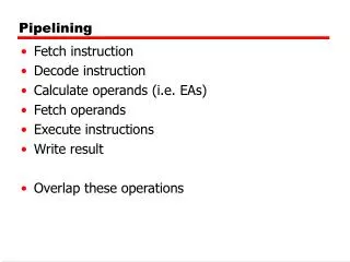
Pipelining. Dr. Javier Navaridas javier.navaridas@manchester.ac.uk. COMP25212 System Architecture. From Tuesday…. What is pipelining? Dividing execution logic into stages and storing state between stages so that different instructions can be at different stages of processing

E N D
Pipelining Dr. Javier Navaridas javier.navaridas@manchester.ac.uk COMP25212 System Architecture
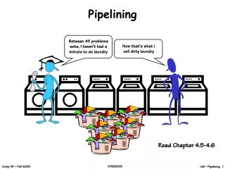
From Tuesday… • What is pipelining? • Dividing execution logic into stages and storing state between stages so that different instructions can be at different stages of processing • What are its benefits? • Pipelining improves the performance by allowing to increase the frequency and enables better logic utilization as all stages will do useful work
From Tuesday … • What is a Control Hazard? • When a branch is executed in a pipeline, the CPU does not know it is a branch until the ID stage. By that time other instructions had been fetched and need to be removed or marked as useless to avoid unexpected changes to the state. This slows processing down • How can we mitigate Control Hazards’ negative effects? • There are many Branch prediction techniques that can be used to predict when a branch will be fetched and its target. If prediction is right, then no cycle is wasted
Data Hazards Pipeline can cause other problems Consider ADD R1,R2,R3 MUL R0,R1,R1 The ADD produces a value in R1 The MUL uses R1 as input There is a data dependencybetween them R2 R3 ADD R1 MUL R0
Instructions in the Pipeline MUX Data Cache IF ID EX MEM WB MUL R0,R1,R1 ADD R1,R2,R3 Register Bank Instruction Cache PC ALU The new value of R1 has not been updated in the register bank MUL would be reading an outdated value!!
The Data is not Ready At the end of the ID cycle, MUL instruction should have selected value in R1 to put into buffer at input to EX stage But the correct value for R1 from ADD instruction is being put into the buffer at the output of EX stage at this time It will not get to the input of WB until one cycle later – then probably another cycle to write into register bank
Dealing with data dependencies (I) Detect dependencies in HW and hold instructions in ID stage until data is ready, i.e. pipeline stall Bubbles and wasted cycles again data is produced here MUL can read R1 safely here R1 is written back here
Dealing with data dependencies (II) Use the compiler to try and reorder instructions Only works if we can find something useful to do – otherwise insert NOPs – waste
Dealing with data dependencies (III) MUX Data Cache Result From ADD • We can add extra data paths for specific cases • The output of EX feeds back into the input of EX • Sends the data to next instruction • Control becomes more complex MUL R0,R1,R1 ADD R1,R2,R3 Register Bank Instruction Cache PC ALU
Forwarding In this case, the result we want is ready one stage ahead (EX) of where it was needed (ID) why wait until it goes down the pipeline? But, …what if we have the sequence LDR R1,[R2,R3] MUL R0,R1,R1 LDR = load R1 from memory address R2+R3 Now the result we want will be ready after MEM stage
Pipeline Sequence for LDR Fetch Decode and read registers (R2 & R3) Execute – add R2+R3 to form address Memory access, read from address [R2+R3] Now we can write the value into register R1
More Forwarding MUX Data Cache • MUL has to wait until LDR finishes MEM • We need to add extra paths from MEM to EX • Control becomes even more complex • The dependency imposes one cycle bubble • LDR R1,[R2,R3] MUL R0,R1,R1 Register Bank Wasted cycle Instruction Cache PC ALU
Deeper Pipelines As mentioned previously we can go to longer pipelines Do less per pipeline stage Each step takes less time So clock frequency increases But Greater penalty for hazards More likely to have conflicting instructions down the pipeline More complex control (e.g. forwarding lanes) A trade-off between many aspects needs to be made Frequency, power, area,
Consider the following program which implements R = A^2 + B^2 • LD r1, A • MUL r2, r1, r1 -- A^2 • LD r3, B • MUL r4, r3, r3 -- B^2 • ADD r5, r2, r4 -- A^2 + B^2 • ST r5, R • Draw its dependency diagram • Simulate its execution in a basic 5-stage pipeline without forwarding. • Simulate the execution in a 5-stage pipeline with forwarding.
Where Next? Despite these difficulties it is possible to build processors which approach 1 instruction per cycle (IPC) Given that the computational model imposes sequential execution of instructions, can we do any better than this?
Instruction Level Parallelism Superscalar processors
Instruction Level Parallelism (ILP) Suppose we have an expression of the form x = (a+b) * (c-d) Assuming a,b,c & d are in registers, this might turn into ADD R0, R2, R3 SUB R1, R4, R5 MUL R0, R0, R1 STR R0, x
ILP (cont) The MUL has a dependence on the ADD and the SUB, and the STR has a dependence on the MUL However, the ADD and SUB are independent In theory, we could execute them in any order, or even in parallel ADD R0, R2, R3 SUB R1, R4, R5 MUL R0, R0, R1 STR R0, x
The Dependency Grapha.k.a. Data Flow graph We can see this more clearly if we plot it as a dependency graph (or data flow) R2 R3 R4 R5 As long as R2, R3, R4 & R5 are available, We can execute the ADD & SUB in parallel ADD SUB MUL x
Amount of ILP? This is obviously a very simple example However, real programs often have quite a few independent instructions which could be executed in parallel Exact number is clearly program dependent but analysis has shown that 4 is relatively common (in parts of the program anyway)
How to Exploit? We need to fetch multiple instructions per cycle – wider instruction fetch Need to decode multiple instructions per cycle Need multiple ALUs for execution But must use common registers – they are logically the same registers Register bank needs more ports But also access common data cache Data cache needs more ports
Dual Issue Pipeline Two instructions can now execute in parallel (Potentially) double the execution rate Called a ‘Superscalar’ architecture (2-way) I1 I2 Instruction Cache Register Bank MUX ALU Data Cache PC MUX ALU
Register & Cache Access Note the access rate to both registers & cache will be doubled To cope with this we may need a dual portedregister bank & dual ported caches This can be done either by duplicating access circuitry or even duplicating whole register & cache structure
Selecting Instructions To get the doubled performance out of this structure, we need to have independent instructions We can have a ‘dispatch unit’ in the fetch stage which uses hardware to examine instruction dependencies and only issue two in parallel if they are independent
Instruction dependencies If we had ADD R1,R1,R0 MUL R2,R1,R1 ADD R3,R4,R5 MUL R6,R3,R3 Issued in pairs as above Data dependencies will limit our opportunities for exploiting parallelism ADD MUL ADD MUL
Instruction reorder If we examine dependencies and reorder ADD R1,R1,R0 ADD R1,R1,R0 MUL R2,R1,R1 ADD R3,R4,R5 ADD R3,R4,R5 MUL R2,R1,R1 MUL R6,R3,R3 MUL R6,R3,R3 We can now execute pairs in parallel (assuming appropriate forwarding logic) ADD ADD MUL MUL
R2 R3 R4 R5 ADD SUB R3 R4 MUL MUL STR STR x y Example of 2-way SuperscalarDependency Graph ADD R0, R2, R3 SUB R1, R4, R5 MUL R0, R0, R1 STR R0, x MUL R2, R3, R4 STR R2, y ADD R0, R2, R3 SUB R1, R4, R5 MUL R0, R0, R1 MUL R2, R3, R4 STR R0, x STR R2, y
Limits of ILP Modern processors are up to 4-way superscalar (but rarely achieve 4x speed) Not much beyond this Hardware complexity Limited amounts of ILP in real programs Limited ILP not surprising, conventional programs are written assuming a serial execution model
Consider the following program which implements R = A^2 + B^2 + C^2 + D^2 • LD r1, A • MUL r2, r1, r1 -- A^2 • LD r3, B • MUL r4, r3, r3 -- B^2 • ADD r11, r2, r4 -- A^2 + B^2 • LD r5, C • MUL r6, r5, r5 -- C^2 • LD r7, D • MUL r8, r7, r7 -- D^2 • ADD r12, r6, r8 -- C^2 + D^2 • ADD r21, r11, r12 -- A^2 + B^2 + C^2 + D^2 • ST r21, R • The current code is not really suitable for a superscalar pipeline because of its • low instruction-level parallelism • Reorder the instructions to exploit superscalar execution. Assume all kinds of forwarding are implemented.
Compiler Optimisation Reordering can be done by the compiler If compiler can not manage to reorder the instructions, we still need hardware to avoid issuing conflicts (stall) But if we could rely on the compiler, we could get rid of expensive checking logic This is the principle of VLIW (Very Long Instruction Word)[1] Compiler must add NOPs if necessary [1] You can find an introduction to VLIW architectures at: https://web.archive.org/web/20110929113559/http://www.nxp.com/acrobat_download2/other/vliw-wp.pdf
Compiler limitations There are arguments against relying on the compiler Legacy binaries – optimum code tied to a particular hardware configuration ‘Code Bloat’ in VLIW – useless NOPs Instead, we can rely on hardware to re-order instructions if necessary Out-of-order processors Complex but effective
Out of Order Processors • An instruction buffer needs to be added to store all issued instructions • A dynamic scheduler is in charge of sending non-conflicted instructions to execute • Memory and register accesses need to be delayed until all older instructions are finished to comply with application semantics
Out of Order Execution Schedule Memory Queue Dispatch Delay Instruction Buffer MUX Register Queue Delay • What changes in an out-of-order processor • Instruction Dispatching and Scheduling • Memory and register accesses deferred Instr. Cache Data Cache PC Register Bank ALU
Consider a simple program with two nested loops as the following: • while (true) { • for (i=0; i<x; i++) { • do_stuff • } • } • With the following assumptions: • do_stuff has 20 instructions that can be executed ideally in the pipeline. • The overhead for control hazards is 3-cycles, regardless of the branch • being static or conditional. • Each of the two loops can be translated into a single branch instruction. • Calculate the instructions-per-cycle that can be achieved for different values of x (2, 4, 10, 100): • Without branch prediction. • b) With a simple branch prediction policy - do the same as the last time.