Download
1 / 81
810 likes | 911 Views
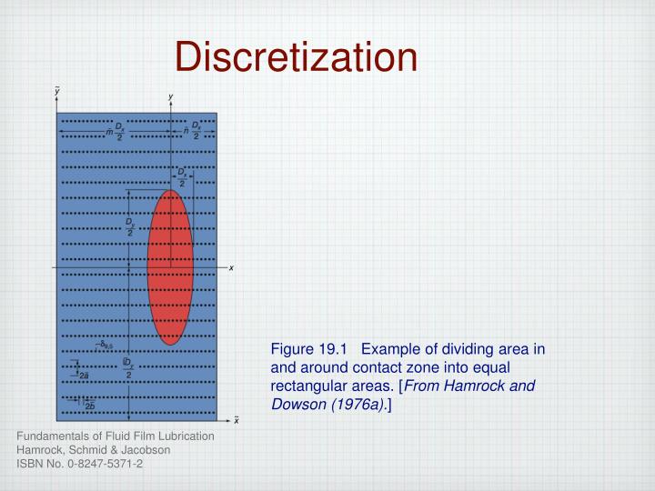
Discretization. Figure 19.1 Example of dividing area in and around contact zone into equal rectangular areas. [ From Hamrock and Dowson (1976a). ]. Film Profile. Where. Figure 19.2 Components of film thickness for elliptical solid near plane. [From Hamrock and Dowson (1981).].

E N D
Discretization Figure 19.1 Example of dividing area in and around contact zone into equal rectangular areas. [From Hamrock and Dowson (1976a).]
Film Profile Where Figure 19.2 Components of film thickness for elliptical solid near plane. [From Hamrock and Dowson (1981).]
Hard EHL Results Figure 19.3 Contour plot of dimensionless pressure with ellipticity parameter k = 1.25 and dimensionless speed, load, and materials parameters held fixed at U = 0.168 x 10⁻¹¹, W=0.111 x 10⁻⁶, and G = 4522. [From Hamrock and Dowson (1977a).] Figure 19.4 Contour plot of dimensionless film thickness with ellipticity parameter k = 1.25 and dimensionless speed, load, and materials parameters held fixed at U = 0.168 x 10⁻¹¹, W=0.111 x 10⁻⁶, and G = 4522. [From Hamrock and Dowson (1977a).]
Comparison of Theory & Experiment Figure 19.5 Theoretical and experimental central and minimum film thickness for pure sliding for two dimensionless load parameters W. (a) W = 0.1238 x 10⁻⁶; (b) W = 0.9287 10-6. [From Kunz and Winer (1977).]
Experimental Verification Figure 19.6 Effect of velocity on central film thickness at constant load (2.6 N) for mineral oil and water-glycol lubricants of similar viscosity. [From Dalmaz and Godet (1978).] Figure 19.7 Predicted dimensionless minimum film thickness from Hamrock and Dowson (1977a) [Eq. (19.16)] compared with experimental results obtained by Koye and Winer. [From Koye and Winer (1980).]
Experimental Verification (cont.) Figure 19.8 Side-leakage factor for elliptical conjunctions in hard EHL. [From Hamrock and Dowson (1981).] Figure 19.9 Effect of ellipticity parameter on ratio of dimensionless minimum film thickness to line-contact dimensionless minimum film thickness, for EHL high- and low-elastic modulus analyses. [From Hamrock and Dowson (1978).]
Computing Area Figure 19.10 Computing area in and around Hertzian contact zone. [From Hamrock and Dowson (1977b).]
Starvation Results - Pressure Figure 19.11 Contour plots of dimensionless pressure for dimensionless inlet distances m of (a) 4, (b) 2, and (c) 1.25 and for group 1 of Table 19.5. [From Hamrock and Dowson (1977b).]
Starvation Results - Film Thickness Figure 19.11 Contour plots of dimensionless film thickness for dimensionless inlet distances m of (a) 4, (b) 2, and (c) 1.25 and for group 1 of Table 19.5. [From Hamrock and Dowson (1977b).]
Starvation Results - Pressure Figure 19.13 Contour plots of dimensionless pressure for dimensionless inlet distances m of (a) 1.967, (b) 1.333, and (c) 1.033 and for group 3 of Table 19.7. [From Hamrock and Dowson (1979a).]
Starvation Results - Film Thickness Figure 19.13 Contour plots of dimensionless film thickness for dimensionless inlet distances m of (a) 1.967, (b) 1.333, and (c) 1.033 and for group 3 of Table 19.7. [From Hamrock and Dowson (1979a).]
Geometry Effects Figure 20.1 Comparison of geometry effects in four lubrication regimes. [From Jeng et al. (1987).]
Lubrication Regimes Figure 20.2 Maps of lubrication regimes for four values of ellipticity parameter k. (a) k=1/2; (b) k=1. [From Esfahanian and Hamrock (1991).]
Lubrication Regimes (cont.) Figure 20.2 Concluded. (c) k=3; (d) k=6.
Temperature along Centerline Figure 20.3 Lubricant and ball surface temperatures along contact centerline. Sliding speed, 1.40 m/s; load 67 N. [From Winer (1983).]
Surface Roughness Effects Figure 20.5 Effect of surface roughness on average film thickness of EHL contacts. [From Zhu and Cheng (1988).]
Radial Ball Bearings Table 21.1 Characteristics of representative radial ball bearings. [From Hamrock and Anderson (1983).]
Angular-Contact Ball Bearings Table 21.2 Characteristics of representative angular-contact ball bearings (Minimum bore size, 10 mm). [From Hamrock and Anderson (1983).]
Thrust Ball Bearings Table 21.3 Characteristics of representative thrust ball bearings (Relative radial capacity, 0). [From Hamrock and Anderson (1983).]
Cylindrical Roller Bearings Table 21.1 Characteristics of representative cylindrical roller bearings. [From Hamrock and Anderson (1983).]
Spherical Roller Bearings Table 21.5 Characteristics of representative spherical roller bearings. [From Hamrock and Anderson (1983).]
Double Row Spherical Roller Bearings Table 21.6 Characteristics of standardized double row, spherical roller bearings. [From Hamrock and Anderson (1983).]
Spherical Roller Bearings Table 21.7 Characteristics of spherical roller bearings. [From Hamrock and Anderson (1983).]
Tapered Roller Bearings Table 21.8 Characteristics of representative tapered-roller bearings. [From Hamrock and Anderson (1983).]
Radial Ball Bearings Figure 21.1 Cross section through radial single-row ball bearings. [From Hamrock and Anderson (1983).] Figure 21.2 Cross section of ball and outer race, showing race conformity. [From Hamrock and Anderson (1983).]
Contact Angle and Endplay Figure 21.3 Cross section of radial bearing, showing ball-race contact due to axial shift of inner and outer races. (a) Initial position; (b) shifted position. [From Hamrock and Anderson (1983).] Figure 21.4 Free contact angle and endplay as a function of cd/2d for four values of total conformity. [From Hamrock and Anderson (1983).]
Ball Bearing Geometry Figure 21.5 Shoulder height in ball bearing. [From Hamrock and Anderson (1983).] Figure 21.6 Cross section of ball bearing. [From Hamrock and Anderson (1983).]
Crowned Bearings Figure 21.7 (a) Spherical roller (fully crowned) and (b) cylindrical roller (partially crowned). [From Hamrock and Anderson (1983).]
Spherical Roller Bearing Figure 21.9 Schematic diagram of spherical roller bearing, showing diametral play and end-play. [From Hamrock and Anderson (1983).] Figure 21.8 Geometry of spherical roller bearing. [From Hamrock and Anderson (1983).]
Contact Angle and Velocity Figure 21.10 Contact angles in ball bearing at appreciable speeds. [From Hamrock and Anderson (1983).] Figure 21.11 Angular velocities of ball. [From Hamrock and Anderson (1983).]
Ball-Spin Axes Figure 21.12 Ball spin axis orientations for (a) outer- and (b) inner-race control. [From Hamrock and Anderson (1983).]
Tapered Roller Bearing Figure 21.13 Simplified geometry for tapered-roller bearing. [From Hamrock and Anderson (1983).]
Radially Loaded Rolling Element Bearing Figure 21.14 Radially loaded rolling-element bearing. (a) Concentric arrangement; (b) initial contact; (c) interference. [From Hamrock and Anderson (1983).]
Contact and Load Figure 21.15 Contact ellipse in bearing race under load. [From Hamrock and Anderson (1983).] Figure 21.16 Angular-contact ball bearing under thrust load. [From Hamrock and Anderson (1983).]
Back-to-Back Arrangement Figure 21.17 Angular-contact bearings in back-to-back arrangement, shown (a) individually as manufactured and (b) as mounted with preload. [From Hamrock and Anderson (1983).]
Load-Deflection Figure 21.18 Thrust load - axial deflection curve for typical ball bearing. [From Hamrock and Anderson (1983).]
Load and Slip in Contact Ellipse Figure 21.19 Differential slip due to curvature of contact ellipse. [From Hamrock and Anderson (1983).] Figure 21.20 Load components in contact ellipse. [From Hamrock and Anderson (1983).]
Friction Figure 21.21 Frictional resistance of ball in conforming groove. [From Hamrock and Anderson (1983).]
Jet Lubrication Figure 21.22 Effectiveness of proper jet lubrication. Test bearings; 20-mm-bore, angular contact ball bearings; thrust load, 222 N (50 lbf). [From Matt and Gianotti (1966).] Figure 21.23 Placement of jets for ball bearings with relieved rings and tapered-roller bearings. [From Parker (1980).]
Underrace Oiling System Figure 21.24 Underrace oiling system for main shaft bearings on turbofan engine. (a) Cylindrical roller bearing; (b) ball thrust bearing. [From Brown (1970).]
Fatigue Spall Figure 21.25 Typical fatigue spall. [From Hamrock and Anderson (1983).]
Bearing Failure Figure 21.26 Distribution of bearing fatigue failures. [From Hamrock and Anderson (1983).] Figure 21.27 Typical Weibull plot of bearing fatigue failures. [From Hamrock and Anderson (1983).]